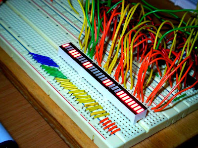
The Arduino only has a maximum of 14 digital outputs (if serial communication is not used) or 12 (if serial communication is used). It is quite easy to extend the number of digital outputs using a 74hc595 serial to parallel shift register.
But the problem with using the 74hc595s is that firstly, the serial data must be clocked out one bit at a time and that in order to change only one of the registers, all of the registers must be written to (because they are all chained together). So there is a limitation in terms of speed and efficiency.
The 74hc374 IC can be used to perform the same function but in a different way. By clocking out data in parallel to all the 74hc374 IC data input lines and then pulsing the clock input of only one of them, it is possible to selectively write to only one of the sets of outputs.
The process is very quick - keep in mind that in order to change the output state of one the ICs, a PORTD or PORTB message can be used to quickly set the entire byte in parallel. Then, the clock input pin of the IC in question simply needs to set high for five microseconds (not milliseconds!) and then low for the same amount of time.
In this context, it is just like using a chip select line and writing to that chip.
This idea can be extended to execute pulse width modulation on, say, thirty-two outputs across four 74hc374 ICs. In the example below, the PWM has a bit depth of eight (as far as the duty cycle is concerned).
Example Video
http://www.youtube.com/watch?v=ioDDVLI9cpQ
Schematic
 Notes about the schematic:
• R1 to R32 should be calculated based on your power supply voltage and the rating of the LEDs you're using.
• PORTD refers to Arduino digital pins 0 to 7.
• PORTB refers to Arduino digital pins 8 to 13.
Breadboard


Code
/*
3 LED Fader using Flip-Flops
by Sebastian Tomczak
27 January 2007
*/
int strobe_time = 5;
void setup() {
DDRD = B11111111;
DDRB = B00111111 | DDRB;
PORTB = B00000000;
}
void write374(byte clkPin, byte data) {
PORTD = data;
digitalWrite(clkPin, HIGH);
delayMicroseconds(strobe_time);
digitalWrite(clkPin, LOW);
delayMicroseconds(strobe_time);
}
void loop() {
for(int loop1 = 0; loop1 < 4; loop1++) {
randomSeed(analogRead(0));
int a = random(255);
randomSeed(analogRead(1));
int b = random(255);
randomSeed(analogRead(2));
int c = random(255);
randomSeed(analogRead(3));
int d = random(255);
for(int k = 0; k < 256; k++) {
for(int i = 0; i < 3; i ++) {
delayMicroseconds(k * 10);
write374(8, a);
write374(9, b);
write374(10, c);
write374(11, d);
delayMicroseconds(2551 - (k * 10) + 1);
write374(8, 0);
write374(9, 0);
write374(10, 0);
write374(11, 0);
}
}
}
for(int j = 0; j < 256; j++) {
int a = 255 | j;
int b = j;
int c = 255 & j;
int d = 255 - j;
for(int k = 256; k > 0; k--) {
for(int i = 0; i < 3; i ++) {
delayMicroseconds(k * 10);
write374(8, a);
write374(9, 0);
write374(10, c);
write374(11, 0);
delayMicroseconds(2551 - (k * 10));
write374(8, 0);
write374(9, b);
write374(10, 0);
write374(11, d);
}
}
}
}


5 comments:
hi Seb,
like this project..:)
however, I'm wondering hou you dealt with the total current. Assuming that each LED is 20mA, 32 of these LEDs is quite a lot for the Arduino (USB powered)..
thanks,
warpie
oh, hey Warpie, how are you going?
basically, i never have all 32 fully on at once. also, keep in mind that this is a fader, and that even when all appear to be on, i might have some PWM so that they are not actually all on at the same time.
i guess if i were using more LED's or trying to power all of them on maybe a wall wart might be an option?
Great project! How far can I take this concept? I am thinking of making a clock with 132 leds (12 hr + 60 min + 60 sec). How can I connect more than 4 of the shift registers (looks like I would need 17 of them)? Is this even doable?
Thanks!
Seb,
I know this post is pretty old, but this is exactly what I want to do. I want to have 7 LEDS all "breathe/fade in and out" at the same time. Doing it with 1 LED is easy and you can do it with PWM and analogWrite using just the Arduino.
I'd like to understand how the 374 chip is doing the PWM for all the 1Q-8Q outputs.
From the looks of the code, you are sending an integer (lets say 255) over the data line and its being transmitted to the 374 as 8 binary bits 11111111. So, is the 374 sending the 255 integer to each Q output? This is what I don't understand. If the answer is Yes, then it makes sense. If the answer is no, then how are all the Q outputs "dimming" at the same time.....?
Thanks.
-J
Goodness, there is a lot of worthwhile info in this post!
Post a Comment