
Wednesday, June 25, 2025
Saturday, April 26, 2025
Max Gen Filter Cookbook

256 tap manual finite response filter
https://github.com/little-scale/littlescale-max-patches/blob/master/manual_fir_filter.maxpat

Morphing-type biquad filter
https://github.com/little-scale/littlescale-max-patches/blob/master/biquad_testing.maxpat
https://github.com/little-scale/littlescale-max-patches/blob/master/biquad-full-basic.gendsp

12 stage biquad lowpass with outputs at 12, 48, 96 and 144 db per octave
https://github.com/little-scale/littlescale-max-patches/blob/master/duodecim-biquad.maxpat
https://github.com/little-scale/littlescale-max-patches/blob/master/duodecim-biquad.gendsp

50 stage single pole lowpass
https://github.com/little-scale/littlescale-max-patches/blob/master/singlepole-cascading.maxpat
https://github.com/little-scale/littlescale-max-patches/blob/master/singlepole.gendsp
https://github.com/little-scale/littlescale-max-patches/blob/master/singlepole.maxpat

Basic biquad implementation of lpf, hpf, bpf, notch, all, shelves in one gen~ patch
https://github.com/little-scale/littlescale-max-patches/blob/master/biquad-full-basic.maxpat
https://github.com/little-scale/littlescale-max-patches/blob/master/biquad-full-basic.gendsp

Moog-style ladder filter with resonance and saturation
https://github.com/little-scale/littlescale-max-patches/blob/master/ladder-filter.maxpat
https://github.com/little-scale/littlescale-max-patches/blob/master/ladder-filter.gendsp

Harmonic resonant bandpass bank with 16 partials and controls for central partial and gain spread.
https://github.com/little-scale/littlescale-max-patches/blob/master/reson-bpf-harmonic-bank.maxpat
https://github.com/little-scale/littlescale-max-patches/blob/master/reson-bpf-harmonic-bank.gendsp

Resonant bandpass filter
https://github.com/little-scale/littlescale-max-patches/blob/master/reson-bpf.maxpat
https://github.com/little-scale/littlescale-max-patches/blob/master/reson-bpf.gendsp
%20filter%20with%20LFO%20modulation.jpeg)
Third order (3ff / 3fb) filter with LFO modulation across all co-efficients
https://github.com/little-scale/littlescale-max-patches/blob/master/filter-3ff-3fb.maxpat
Friday, November 24, 2023
ArUco2osc
Send ArUco marker detections as OSC messages
Download here: https://github.com/little-scale/ArUco2osc
Repo contains 50 4x4 markers


To use:
- pip install opencv-contrib-python
- pip install python-osc
- python aruco2osc.py
Args are:
- --input: camera to use; default 0
- --address: OSC message address to use; default /aruco/marker
- --ip: OSC IP address to use; default 127.0.0.1
- --port: OSC port to use; default 3001
Each message contains:
- marker identity
- size as a normalised ratio
- angle in degrees
- x value of midpoint of marker as a normalised value
- y value of midpoint of marker as a normalised value

Thursday, November 16, 2023
Mediapipe Holistic Solution to OSC

Taking the legacy Mediapipe holistic solution (face + pose + left hand + right hand) and sending all 543 landmarks via OSC to Max or other places.
Tuesday, December 13, 2022
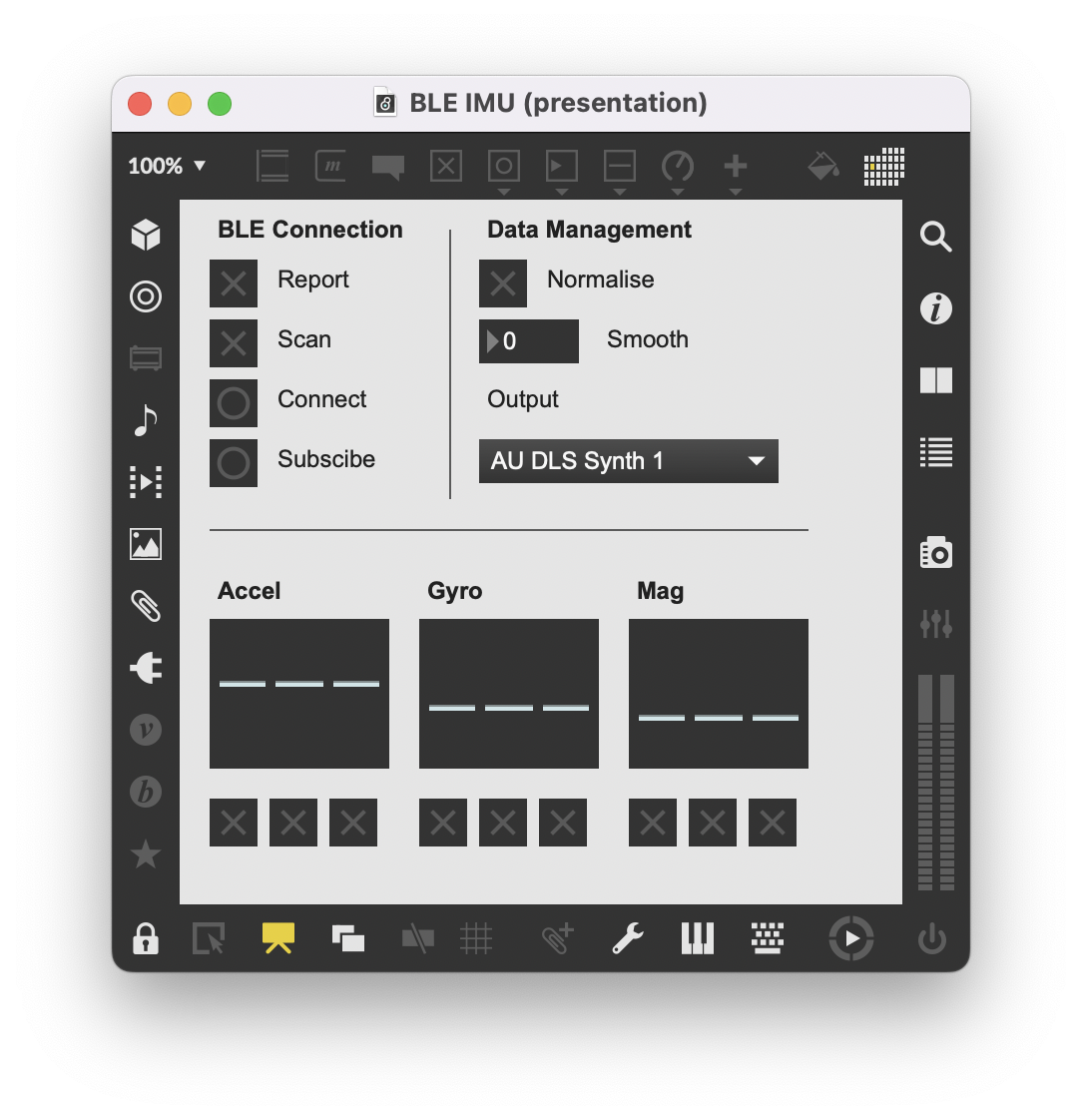
Sending Inertia Motion Unit Data of Arduino Nano BLE 33 over Bluetooth BLE
This Arduino sketch and Max patch takes the inertia motion unit data of the Nano BLE 33 and sends it via Bluetooth BLE using the ArduinoBLE library. The data is transferred as a set of BLE Characteristics as a BLE Service. The Max patch scans for the BLE device, connects to it and then subscribes to the data streams. The output can be normalised, smoothed and then routed via MIDI to music software such as Ableton. The Max patch uses the max-ble external.
Get the Arduino code here, the Max patch here and the 4bf subpatch here.
With Bluetooth Low Energy (BLE), devices do not need to pair in order to communicate data. Instead, a paradigm of central and peripheral devices is used. Central devices scan for Peripheral devices and initiate connections. Peripheral devices advertise their BLE Services and wait for a Central device to connect. In this example, the computer running the Max patch is the Central and the Arduino Nano BLE 33 is the Peripheral.
A given Service on a Peripheral device is made up of one or more Characteristics. A Characteristic contains one or more bytes of data and may be part of a standard profile or a generic type with customised data length. Each Service and Characteristic has a UUID unique identifier that is either a 16-bit or 128-bit string. The Arduino BLE library contains a number of functions to create a BLE Service and Characteristic.
This setup combines the following:
- In Arduino, start the BLE radio as a Peripheral device, create a Service with a UUID for the IMU data and then create three Characteristics each with a UUID - one each for the accelerometer, gyroscopic and magnetometer
- Read the accelerometer, gyroscopic and magnetometer values using the 9-axis LSM9DS1 inertia motion unit
- Then, using a data struct for the x, y and z axes the current values from the 9-axis IMU are stored as floats (if there are new readings available)
- The data struct for each inertia type is stored in a data union that is also addressable by a byte array
- This byte array from the union, which now contains the updated float values from the IMU, is then read and written to the BLE Characteristic which automatically Notifies the Central device
- The Max patch acts as the Central device and can scan for devices with the correct UUID
- Once the correct UUID is found from the scan, a connection can be made
- Once the connection has been made, each of the three characteristics can be Subscribed to
- Every time a new value is written to the Characteristic, the Central device is Notified and if the Max patch is Subscribed to this Characteristic, the new data values are received in Max by the max-ble object
- In this case, each Characteristic contains a float value for the x, y and z components for the accelerometer, gyroscopic and magnetometer - making for a total of 3 floats per Characteristic and 3 Characteristics
- Each of these floats arrives in Max as a set of four bytes. These four bytes are then converted back to a floating value within Max using the subpatch 4bf.
- This data is then scaled and normalised, so as to be visualised via multisliders
- The data is also smoothed with a user defined ramp time
- Finally, the data can be muted by x, y, z channel and then sent via MIDI CC to other music software


Tuesday, November 27, 2018
Poly to Mono Max Patch

This patch will distribute a single channel of MIDI data to two or more MIDI channels based on polyphonic note order. Options include channel offset, number of voices, sending a C4 to all outputs. Pitch bend is also sent.
Download here: https://github.com/little-scale/littlescale-max-patches/tree/master/poly-to-mono
Tuesday, October 23, 2018
Drum Distribution Max Patch

A Max patch that takes MIDI pitch identities and distributes them to selected MIDI channels.
Download here: https://github.com/little-scale/littlescale-max-patches/tree/master/drum-distribution
Sunday, May 27, 2018
Pitch CV to Frequency Conversion with Offset Opamp and ADC
This method makes a few assumptions:
• That pitch CV signals may be unipolar, with negative voltages and positive voltages
• A user can set the offset via a pot, thereby having a variable range in terms of negative and positive voltages
• The pitch CV signal will be 1 volt per octave
• The pitch CV signal will be roughly a 10v range
12V and -12V power supply rails are required. In this case, the Digilent PowerBrick supplies both from USB 5V. A Eurorack power supply could also deliver 12V and -12V.
The pitch CV signal is summed with an offset voltage. The offset voltage is derived by dividing +12v to -12v with a 10k potentiometer. The sum of both signals is fed into an inverting opamp with unity gain, whose output is fed into a second inverting opamp. The resulting signal is a phase-correct unipolar pitch CV signal (assuming the 10k potentiometer is set correctly) in the range of perhaps 0V to 10V.
This signal is then divided by 3 by using a resistor voltage divider, where 20k is on the input side and 10k goes to ground - this will then equate to 1/3V per octave. The output of this voltage divider is then fed through some clamping diodes (such as 1n4148), to limit the range to 0V - 3.3V. The voltage is then read as a 12-bit analog to digital value.
The value range of the ADC conversion is 0 - 4095, and this represents a voltage range of 0V - 3.3V, which in turn represents a pitch range of 0 to 9.9 octaves (at 1/3V per octave) with a resolution of about 2.9 cents.
The ADC conversion value is mapped to MIDI pitch, giving a range of 120 - 132 semitones. This MIDI note value is then converted to frequency using my Arduino mtof library, which can be downloaded here.
The frequency value could be used to control another synthesiser or oscillator, or used for analysis and further conversion.
In this particular example, the resulting frequency value is sent via two MIDI pitch messages - one for the integer portion and one for the floating portion - and then reconstructed as a frequency value for a sine wave in a Max patch. A comparison can then be made to the analog output of a VCO to see how accurate the pitch conversion is. Note that a scaler value of 1.03 corrects for tuning issues - this value may change depending on setup.
#include <mtof.h>
#include <math.h>

float data;
float pitch;
float pitch_offset = 0;
float freq;

float max_voltage_of_adc = 3.3;
float voltage_division_ratio = 0.3333333333333;
float notes_per_octave = 12;
float volts_per_octave = 1;
float scaler = 1.03;

float mapping_upper_limit = (max_voltage_of_adc / voltage_division_ratio) * notes_per_octave * volts_per_octave * scaler;

void setup() {
  analogReadResolution(12); // 12-bit ADC resolution
}

void loop() {
  data = analogRead(0); // read pitch CV as data value using ADC
  pitch = pitch_offset + map(data, 0.0, 4095.0, 0.0, mapping_upper_limit); // convert pitch CV data value to a MIDI note number
  freq = mtof.toFrequency(pitch); // convert MIDI note number to frequency

  /*  To test out the frequency values that are being generated from pitch cv conversion, the frequency value is sent over MIDI pitch bend.
   *  Pitch bend channel 1 is used for the integer component, and pitch bend channel 2 is used for the float component
   *  The pitch bend messages are re-constituted in a Max patch for testing.
   *  The pitch bend messages are not intended for use with a 'normal' MIDI synth
   *  This is because they used as a way of conveying the data and not as a regular pitch bend message.
  */

  usbMIDI.sendPitchBend(freq, 1); // split up integer part of the frequency and send as a pitch bend value
  usbMIDI.sendPitchBend(fmod(freq, 1.0) * 10000.0, 2);

  delay(1);
}


Pitch CV to Frequency Conversion via Voltage Division and ADC
This method makes a few assumptions:
• That a voltage of 0V is equal to MIDI note 36
• That all pitch CV signals will unipolar, with negative voltages being clamped to 0V
• The pitch CV signal will be 1 volt per octave
• The pitch CV signal will be roughly in the range of 0 - 9.9V
The pitch CV signal is divided by 3 by using a resistor voltage divider, where 20k is on the input side and 10k goes to ground - this will then equate to 1/3V per octave. The output of this voltage divider is then fed through some clamping diodes (such as 1n4148), to limit the range to 0V - 3.3V. The voltage is then read as a 12-bit analog to digital value.
The value range of the ADC conversion is 0 - 4095, and this represents a voltage range of 0V - 3.3V, which in turn represents a pitch range of 0 to 9.9 octaves (at 1/3V per octave) with a resolution of about 2.9 cents.
The ADC conversion value is mapped to MIDI pitch, giving a range of 118.8 semitones. This MIDI note value is then converted to frequency using my Arduino mtof library, which can be downloaded here.
The frequency value could be used to control another synthesiser or oscillator, or used for analysis and further conversion.
In this particular example, the resulting frequency value is sent via two MIDI pitch messages - one for the integer portion and one for the floating portion - and then reconstructed as a frequency value for a sine wave in a Max patch. A comparison can then be made to the analog output of a VCO to see how accurate the pitch conversion is.
#include <mtof.h>
#include <math.h>

float data;
float pitch;
float pitch_offset = 36;
float freq;

float max_voltage_of_adc = 3.3;
float voltage_division_ratio = 0.3333333333333;
float notes_per_octave = 12;
float volts_per_octave = 1;

float mapping_upper_limit = (max_voltage_of_adc / voltage_division_ratio) * notes_per_octave * volts_per_octave;

void setup() {
  analogReadResolution(12); // 12-bit ADC resolution
}

void loop() {
  data = analogRead(0); // read pitch CV as data value using ADC
  pitch = pitch_offset + map(data, 0.0, 4095.0, 0.0, mapping_upper_limit); // convert pitch CV data value to a MIDI note number
  freq = mtof.toFrequency(pitch); // convert MIDI note number to frequency

  /*  To test out the frequency values that are being generated from pitch cv conversion, the frequency value is sent over MIDI pitch bend.
   *  Pitch bend channel 1 is used for the integer component, and pitch bend channel 2 is used for the float component
   *  The pitch bend messages are re-constituted in a Max patch for testing.
   *  The pitch bend messages are not intended for use with a 'normal' MIDI synth
   *  This is because they used as a way of conveying the data and not as a regular pitch bend message.
  */

  usbMIDI.sendPitchBend(freq, 1); // split up integer part of the frequency and send as a pitch bend value
  usbMIDI.sendPitchBend(fmod(freq, 1.0) * 10000.0, 2);

  delay(1);
}


Sunday, February 18, 2018
Thea Musgrave's "Narcissus" for Flute and Electronics Max for Live Patch

A preset file stores and recalls the settings from the score for delay time, feedback and modulation depth. The other parameters need to adjusted manually.

Incrementing the preset number can be mapped in terms of MIDI control, as can the hold button, output level and bypass.

Download here: http://milkcrate.com.au/_other/downloads/M4L/narcissusm4l.zip
Tuesday, November 28, 2017
On Sonifying Local Australian Weather Data in Real Time

These are Adelaide weather observations from the Australian Bureau of Meteorology.

The JSON file, which is found on the above page, can be accessed in Max. Specific data points can be re-loaded and then used to drive sonic parameters. These will update as the Bureau's observations update.
This will work for any of the listed observations parameters, as well as any of the observation locations found on the BOM.
Tuesday, November 07, 2017
Max for Live UDP OSC Packet to MIDI Message Receiver

A simple receiver device in Max for Live that takes an OSC message (via a selected UDP port) and simply sends the data bytes from this message as a MIDI message. Naturally, it is assumed that the OSC message itself contains data bytes formatted as a MIDI message.
Download here: http://milkcrate.com.au/_other/downloads/M4L/little-scale.osc.packet.to.midi.message.amxd
Friday, January 27, 2017

Thursday, January 19, 2017
Ableton Link to Teenage Engineering PO-12 Sync


This is a Max patch that connects to an Ableton Link network, and generates pulses suitable for a Teenage Engineering Pocket Operator PO-12 or other similar sync scenarios.
Download the Max patch here: http://milkcrate.com.au/_other/downloads/max_patches/Link_to_Pulse_Tick.maxpat
The patch requires Max, which can be run in demo mode as a version of runtime. The patch requires the Max Ableton Link package, which can be installed via the package manager in Max.
The pulses are output via an audio interface. In this case, the audio interface that is used is a $2 (with free shipping) USB sound card.
To use the patch:
- Make sure that the laptop and any Link devices are on the same network
- Launch Max go to Options > Audio Status..., set the audio output device to the audio interface and turn the audio engine on
- Connect the output of the audio interface to the PO-12
- Launch the Link to Pulse Tick patch, and set quantum to 4 and subdivisions to 2
- Set the PO-12 to SY2 (sync input, stereo output) by pressing funct and bpm
- Press play on the PO-12 - the PO-12 will wait for a sync signal
- Enable to the output of the sync patch by turning the toggle on
- At the start of the next quantum (bar), the patch will start sending a sync signal to the PO-12, the PO-12 will play in time with Link
- Changing the tempo in the patch will update all other Link devices on the network and vice versa
Monday, January 16, 2017
Splitting Polyphonic MIDI Across Multiple Channels
How to split MIDI chords and polyphonic note data across multiple monophonic MIDI channels, so that any given channel is only ever playing back one note at a time.
Download the mono.to.poly.dyn Max for Live device here: http://milkcrate.com.au/_other/downloads/M4L/little-scale.Poly.to.Mono.Dyn.amxd
Download the receive.dyn Max for Live device here: http://milkcrate.com.au/_other/downloads/M4L/little-scale.PathMIDI.receive.dyn.amxd
Thursday, January 12, 2017
Poly to Mono Dynamic Voice Allocation in Max for Live

Send polyphonic MIDI data to multiple mono channels by using this Max for Live device in conjunction with the dynamic MIDI receive bussing device.
Download here: http://milkcrate.com.au/_other/downloads/M4L/little-scale.Poly.to.Mono.Dyn.amxd
Monday, December 26, 2016
Wednesday, December 21, 2016
A Simple MiraWeb Example: Controlling Max 7 from a Browser


M4L Device: Oct LFO

Simple and compact eight-oscillator LFO.
Download here: http://milkcrate.com.au/_other/downloads/M4L/little-scale.oct.lfo.amxd.zip
