Showing posts with label physical digital. Show all posts

Wednesday, March 08, 2023

Teensy 4.1 with TMP117 Temperature to USB MIDI

Overview

The TMP117 is a high precision temperature sensor with I2C output and can measure between -55˚C to 150˚C. 


Hardware


The following connections should be made between the Teensy 4.1 and the TMP117:
  • Teensy 4.1 3V to TMP117 VCC - orange in the above photo
  • Teensy 4.1 ground to TMP117 GND - black in the above photo
  • Teensy 4.1 pin 19 / A5 / SCL / PWM to TMP117 SCL - yellow in the above photo
  • Teensy 4.1 pin 18 / A4 / SDA / PWM to TMP117 SDA - yellow in the above photo


In order to set the correct I2C address for the TMP117 device for this code example, make sure the first bit of the four address bits is set and the rest are cleared. 

Software

The Arduino code uses the Wire library to communicate with the TMP117 via the I2C bus. The TMP117-Arduino library by Nils Minor is required and can be installed via the Arduino IDE. If the temperature changes, the new value is sent as a scaled, simple USB MIDI control change message. 

#include "TMP117.h"

double temp;
int data;
int data_prev;
const int chan = 1;
const int cc = 1;

TMP117 tmp(0x48);

void setup() {
Wire.begin();
Serial.begin(115200);
tmp.init(NULL);
}

void loop() {
temp = tmp.getTemperature();
data = constrain(map(temp, 0.0, 48.0, 0.0, 127.0), 0.0, 127.0);
Serial.println(temp);

if (data != data_prev) {
usbMIDI.sendControlChange(cc, data, chan);
delay(10);
}
}


The temperature can be viewed in Max via this example patch: 


Tuesday, December 13, 2022

Sending Inertia Motion Unit Data of Arduino Nano BLE 33 over Bluetooth BLE

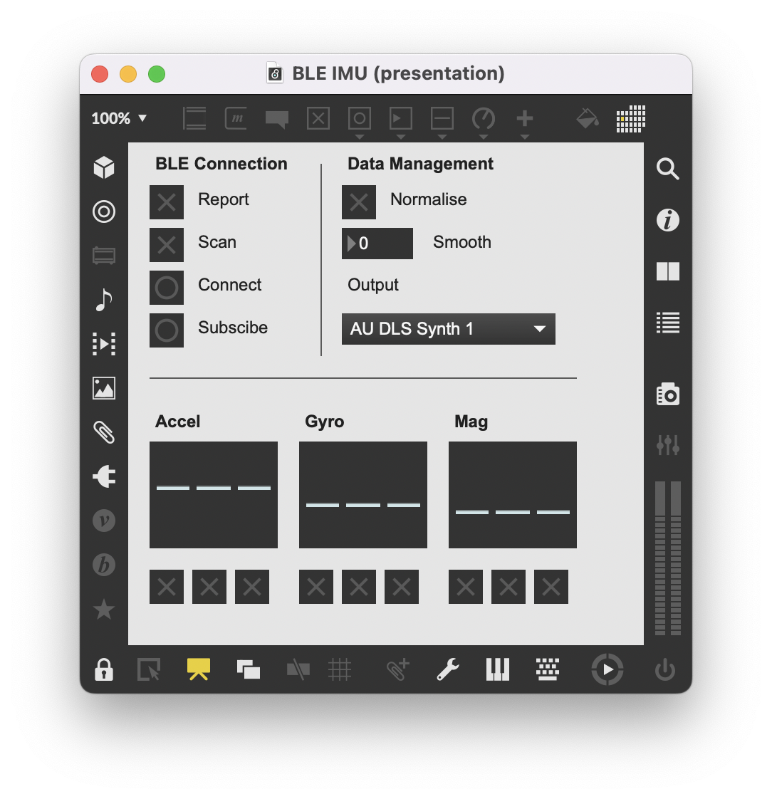
This Arduino sketch and Max patch takes the inertia motion unit data of the Nano BLE 33 and sends it via Bluetooth BLE using the ArduinoBLE library. The data is transferred as a set of BLE Characteristics as a BLE Service. The Max patch scans for the BLE device, connects to it and then subscribes to the data streams. The output can be normalised, smoothed and then routed via MIDI to music software such as Ableton. The Max patch uses the max-ble external. 

Get the Arduino code here, the Max patch here and the 4bf subpatch here

With Bluetooth Low Energy (BLE), devices do not need to pair in order to communicate data. Instead, a paradigm of central and peripheral devices is used. Central devices scan for Peripheral devices and initiate connections. Peripheral devices advertise their BLE Services and wait for a Central device to connect. In this example, the computer running the Max patch is the Central and the Arduino Nano BLE 33 is the Peripheral. 

A given Service on a Peripheral device is made up of one or more Characteristics. A Characteristic contains one or more bytes of data and may be part of a standard profile or a generic type with customised data length. Each Service and Characteristic has a UUID unique identifier that is either a 16-bit or 128-bit string. The Arduino BLE library contains a number of functions to create a BLE Service and Characteristic


This setup combines the following: 

  • In Arduino, start the BLE radio as a Peripheral device, create a Service with a UUID for the IMU data and then create three Characteristics each with a UUID - one each for the accelerometer, gyroscopic and magnetometer
  • Read the accelerometer, gyroscopic and magnetometer values using the 9-axis LSM9DS1 inertia motion unit
  • Then, using a data struct for the x, y and z axes the current values from the 9-axis IMU are stored as floats (if there are new readings available) 
  • The data struct for each inertia type is stored in a data union that is also addressable by a byte array
  • This byte array from the union, which now contains the updated float values from the IMU, is then read and written to the BLE Characteristic which automatically Notifies the Central device
  • The Max patch acts as the Central device and can scan for devices with the correct UUID
  • Once the correct UUID is found from the scan, a connection can be made
  • Once the connection has been made, each of the three characteristics can be Subscribed to
  • Every time a new value is written to the Characteristic, the Central device is Notified and if the Max patch is Subscribed to this Characteristic, the new data values are received in Max by the max-ble object
  • In this case, each Characteristic contains a float value for the x, y and z components for the accelerometer, gyroscopic and magnetometer - making for a total of 3 floats per Characteristic and 3 Characteristics 
  • Each of these floats arrives in Max as a set of four bytes. These four bytes are then converted back to a floating value within Max using the subpatch 4bf. 
  • This data is then scaled and normalised, so as to be visualised via multisliders
  • The data is also smoothed with a user defined ramp time
  • Finally, the data can be muted by x, y, z channel and then sent via MIDI CC to other music software


Wednesday, May 17, 2017

Teensy 3.6 Basics - Using DC Motors

Overview
DC motors rotate when a voltage is applied across the terminals. The speed of the motor is related to the voltage.

When using a microcontroller to control a DC motor a PWM (or pulse width modulated) signal is used. The Teensy forms a pulse wave, whereby the duty cycle is proportional to the average, equivalent over time. The duty cycle refers to the percentage of the waveform that the pulse wave is high as opposed to low.

A PWM output with a duty cycle of 50% will result in an average of half the voltage of the digital pin, a duty cycle of 25% in one quarter and so on. More information can be found about PWM signals here.

For instance, given a 3V digital pin with a PWM wave of 50%, this would provide the equivalent voltage of 1.5V over time. Thus, the digital PWM outputs on a Teensy can change the speed of a DC motor, not just turn it off and on.

The default frequency for PWM signals on the Teensy 3.6 is 488.28 Hz. Digital outputs 2, 3, 4, 5, 6, 7, 8, 9, 10, 14, 16, 17, 20, 21, 22, 23, 29, 30, 35, 36, 37, 38 are all PWM-capable pins. More information about the PWM functionality of the Teensy can be found here.

When using a PWM signal to control a motor, a certain amount of current is needed to power the motor. The outputs of the Teensy cannot provide sufficient current for the DC motor, and attempting to do so may damage the Teensy.

Instead, a Darlington transistor array in a convenient chip form can manage power source, current and control input and act as mediator between the teensy, the USB power and the DC motor. Note that anything more heavy duty than a very light motor will require an external power supply.

The Darlington transistor array comes packaged in an 8-channel version (ULN2803AN) and 7-channel version (ULN2003AN). In both cases, multiple channels can be combined to control larger motors. Each channel can provide up to 500mA of current, if a sufficient power supply is used.

In the example shown below, a single channel of a ULN2803AN is used to drive a single DC motor using 3V from the Teensy USB power supply.


Hardware Setup


Ground from the Teensy is connected to pin 9 of the ULN2803AN. 3V from the Teensy is connected to pin 10 of the ULN2803AN. Digital pin 2 of the Teensy is connected to pin 1 of the ULN2803AN. Pin 18 of the ULN2803AN is connected to one terminal of the motor. 3V from the Teensy is connected to the other terminal of the motor.


Software Setup
To control the motor, make sure that the motor is connected to a PWM-capable pin. Digital outputs 2, 3, 4, 5, 6, 7, 8, 9, 10, 14, 16, 17, 20, 21, 22, 23, 29, 30, 35, 36, 37, 38 are all PWM-capable pins.

Use analogWrite(pin, value) to set the speed of the motor. The pin is the pin number. The value is a range of 0 - 255.

There is no need to set the pin as an output pin in setup().


Example 1 - Turning the DC Motor On and Off
The motor is turned on and off.


Example 2 - Gradually Turning the DC Motor On Over Time

Download here: http://milkcrate.com.au/_other/downloads/arduino/teensy_3_6_basics/Using_DC_Motors_Example_2/


Summary
DC motors can be easily controlled via analogWrite(), however they require additional hardware to work. Combined with MIDI control, there can be used in projects of various types.

Teensy 3.6 Basics - Using Servo Motors

Overview
A servo motor is a physical actuator that usually rotates for half a circle or less, or moves forwards and backwards by a set amount. Arduino add-on includes a servo library, which can be used to easily control a servo motor.

A simple, lightweight servo motor can be connected and powered by the Teensy 3.6. Note that anything more heavy duty than a very light motor will require an external power supply.

A servo motor has a control input, which expects a pulse wave with a duty cycle of around 1 - 2 ms and a period length of 20 ms. The duty cycle determines the angle or position of the servo. A duty cycle of 1 ms sets the minimum rotation or position. A duty cycle of 2 ms sets the maximum rotation or position.


Hardware Setup
The servo motor has three connections. Black or brown is usually ground, and should be connected to Teensy ground. Red is usually the positive power terminal, and should be connected to Teensy 3.3V. Orange or yellow is usually the control input, and should be connected to a Teensy digital pin, in this case pin 0.

Note that if a more heavy-duty servo motor is used, an external power supply is required. In this case, the ground of the motor, teensy and power supply should be connected. The positive terminal of the power supply should be connected to the positive terminal of the servo. The control input should be connected to a Teensy digital pin.


Software Setup 
The servo library must be included at the start of the code. A servo object with a unique name can then be created by using the Servo structure.

The servo object can then be attached to a digital pin of the Teensy. This can be any digital pin. Two optional arguments as part of attaching the pin set the minimum and maximum duty cycle time periods in microseconds. A suggestion is to start with 1000 microseconds and 2000 microseconds, and adjust from there.

To control the servo motor, the write command is used with the Servo object. The value is in degrees, from 0 - 180.


Example 1 - Rotating the Servo
In this example, a servo is connected to the Teensy. The servo is then simply rotated and delayed on loop via the servo library.


Download here: http://milkcrate.com.au/_other/downloads/arduino/teensy_3_6_basics/Using_Servos_Example_1/


Example 2 - Controlling the Servo via MIDI
In this example, the servo is controlled via a MIDI control message on channel 1, controller 1. The range of 0 - 127 is mapped to 0 - 180 degrees.


Download here: http://milkcrate.com.au/_other/downloads/arduino/teensy_3_6_basics/Using_Servos_Example_2/


Summary
The servo motor is an example of physical control via the Teensy. MIDI data can be used to control the movement of the motor.

Monday, December 12, 2016

Visual Data with Recording: Arduino Sensors, Max and CSV Files

Sunday, December 11, 2016

Simple Data Visualisation and Recording

I find it useful to be able to visualise data - especially when dealing with sensor data. This includes things like a current-state graphical representation, scrolling graphs and the ability to import sensor data into Excel for further analyses or record keeping.


Download here: http://milkcrate.com.au/_other/downloads/max_patches/simple_data_vis_rec.maxpat

This Max patch is simply a visualisation tool that takes up to sixteen channels of data via MIDI pitch bend messages and displays this as a set of sliders, a scrolling point graph and the ability to export to a text file that can be imported into Excel (tab-deliminated with carriage returns).

Peak values can be shown as orange markers on the sliders. The peak data can be cleared. Data that is fed into the scrolling point display as well as the text file has an interval / sampling rate. This is between 0 - 10000 milliseconds as defined by the user. This interval / sampling rate is independent of the rate and which data arrives, which is handy of asynchronous data across multiple channels.

Data per channel can be toggled on or off for the text file recording. The text file can be viewed, cleared and saved to disk. To import the text file into Excel, simply select open from Excel, choose tab-deliminated CSV file, choose tab as the separator. This will present the data via columns as channels, rows as sample periods and cells as data points. From here, the data can be manipulated as per usual in Excel.

To send data in the correct format, simply send a 14-bit MIDI value from software or hardware to the Max patch. Make sure that the correct MIDI device is selected in the patch. The pitch bend from each MIDI channel is a separate data channel in the patch, from 1 - 16.

Data can be sent from Live, Logic, ProTools etc. Data can also be sent from hardware such as MIDI controllers and keyboards.

Data can also be sent from Arduino / Teensy etc. Here is the Teensy code as an example - the important thing to realise is that each sensor's data is sent on a MIDI channel via pitch bend, and that the data is constrained to a 0 - 16383 value range.


Saturday, July 30, 2016

Simple MIDI Rotary Encoder with Teensy / Arduino

Overview
A rotary encoder uses digital encoding of pulses in either a clockwise or counter-clockwise direction to determine relative location. This particular rotary encoded includes a push button as part of the shaft. 

This example shows how to connect a single, simple rotary encoder, and use the output as a MIDI controller.


Hardware
This particular encoder has five pins. The group of three pins on one side is the encoder. The group of two pins on the other side is the


For the group of three encoder pins, connect the right hand pin to a digital pin on the Teensy. In this case, pin 2 has been chosen. Connect the left hand pin to a digital pin on the Teensy. In this case, pin 3 has been chosen. Connect the middle of the three pins to ground.

These particular pins have been selected because they support interrupts on the Teensy LC. Refer to the Teensy pinouts to see possible pins, labelled INT. Note that Teensy 3.1 and 3.2 support interrupts on all digital pins.

For the group of two button pins, connect one pin to a digital pin on the Teensy and the other pin to ground.


Software


Download here: http://milkcrate.com.au/_other/downloads/arduino/Teensy_Rotary_Encoder.ino

The code uses the encoder library, which is included with the Teensyduino install. The encoder is mapped to MIDI CC #1 channel 1, and is constrained to 0 - 127. The button is mapped to MIDI CC#2 channel 1.


Video

Tuesday, June 14, 2016

Pear Theremin

A pear is connected to pin 0 on the Teensy LC. The touchRead function is mapped to pitchbend via USB MIDI. A pitchbend oscillator in Max for Live / Ableton is used to map the pitchbend to frequency.


Monday, June 13, 2016

Mandarin Music Keyboard


Mandarins are attached to pins 0, 1, 3, 4, 18, 19, 22 and 23. The touchRead function is used to read the values. Note on / note off and modulation wheel data is sent via USB.

Download the Arduino code here: http://milkcrate.com.au/_other/downloads/arduino/touchMandarins.ino
 

Monday, May 30, 2016

MCP4241 Digital Pot and Teensy LC

Overview
The MCP4241 chip is a digital pot. Digital pots are versatile devices that can be used to control a variety of circuits, replacing traditional potentiometers.

The MCP4241 uses an SPI bus. The Teensy LC can be used to control the MCP4241 chip in a straightforward manner.

The MCP4241-104E is a chip with 100k digitally controlled pots that are accessed via an SPI bus. Additionally, the chip features both volatile and non-volatile memory and a number of other useful functions. The pots have 7-bits of resolution (i.e. 128 steps of resistance). It can be powered from 2.7V to 5.5V.

The MCP4241 comes from a larger family of chips, the MCP414X/416X/424X/426X family. More information can be found here.


The SPI Bus
The MCP4241 connects and communicates with a microcontroller (such as an Arduino or a Teensy) via the SPI Bus. SPI is a protocol that allows microcontrollers to interface easily with a large number of external chips and sensors.

SPI is a host / slave type bus. A single host microcontroller can interface with one or more slave chips or sensors.

SPI uses up to four pins for communication:
- CS (may also be called SS): chip select:
Used by the microcontroller to select each device. The host microcontroller has a CS output pin for every slave device that is to be used.

- SCK: serial clock:
Used by the host microcontroller to time the data that is moved to and from the slave device. There is one SCK connection that is shared amongst all SPI devices.

- SDI: slave data in:
Used by the host microcontroller to send data to a slave device. There is one SDI connection that is shared amongst all SPI devices.

- SDO: slave data out:
Used by the host microcontroller to receive data from a slave device. There is one SDO connection that is shared amongst all SPI devices.

All SPI slave devices require the CS and SCK pins. However, many device may not require both the SDI and SDO connections, as they might only either send or receive data.

With the MCP4241 chip, we want to set the resistance of a digital potentiometer using data from a host microntroller. As a result, we only need CS, SCK and SDI, because the information needs to travel only from the host to the slave device.

If you are using a Teensy, the following table shows the CS, SCK, SDI and SDO pins to use:


If you are using an Arduino, the following table shows the CS, SCK, SDI and SDO pins to use:

If you are using a Teensy, the following table shows the pins to us:


MCP4241 Physical Layout


The above diagram shows the layout of the 14-pin MCP4241 chip. Pin 1 is to the left of the half-circle indent. Pin 14 is to the right of the half-circle indent.

Pin 1 - CS - SPI Bus Chip Select
Pin 2 - SCK - SPI Bus Serial Clock
Pin 3 - SDI - SPI Bus Slave Digital In
Pin 4 - Vss - Connect to Ground
Pin 5 - P1B - Potentiometer Number 1, Terminal B
Pin 6 - P1W - Potentiometer Number 1, Wiper
Pin 7 - P1B - Potentiometer Number 1, Terminal A
Pin 8 - P0B - Potentiometer Number 0, Terminal A
Pin 9 - P0W - Potentiometer Number 0, Wiper
Pin 10 - P0B - Potentiometer Number 0, Terminal B
Pin 11 - WP - Write Protection - Connect to VCC for normal operation
Pin 12 - SHDN - Shutdown - Connect to VCC for normal operation
Pin 13 - SDO - SPI Bus Slave Digital Out
Pin 14 - Vdd - Connect to VCC


Connecting to Teensy LC


MCP4241 Pin 1 - CS - SPI Bus Chip Select - connect to Teensy LC digital pin 10 - green wire
MCP4241 Pin 2 - SCK - SPI Bus Serial Clock - connect to Teensy LC digital pin 13 - green wire
MCP4241 Pin 3 - SDI - SPI Bus Slave Digital In - connect to Teensy LC digital pin 11 - green wire
MCP4241 Pin 4 - Vss - Connect to Ground - connect to Teensy LC ground
Pin 5 - P1B - Potentiometer Number 1, Terminal B
Pin 6 - P1W - Potentiometer Number 1, Wiper
Pin 7 - P1B - Potentiometer Number 1, Terminal A
Pin 8 - P0B - Potentiometer Number 0, Terminal A
Pin 9 - P0W - Potentiometer Number 0, Wiper
Pin 10 - P0B - Potentiometer Number 0, Terminal B
Pin 11 - WP - Write Protection - connect to Teensy LC 3V
Pin 12 - SHDN - Shutdown - connect to Teensy LC 3V
Pin 13 - SDO - SPI Bus Slave Digital Out - not required for basic operation
Pin 14 - Vdd - connect to Teensy LC 3V


Programming 
The MCP4241 is easily programmed. Please see below for an example that increases the resistance of the pot by a value of 1 every 100 milliseconds.


The pot can be tested by uploading this program to the Teensy LC, and then measuring the resistance between 6 and 7.

Tuesday, May 24, 2016

MIDI Controlled Servo Motor

Tuesday, November 17, 2015

32 Capacitive Touch Sensors and Ableton Live


Hardware


The hardware is quite straightforward. Two 4067 multiplexers have a common address bus, going from Teensy 3.2 digital pins 0, 1, 2 and 3 to s0, s1, s2 and s3. Teensy 3.3v is connected to VCC on both multiplexers. Teensy ground is connected to both gnd and en on both multiplexers. Sig from multiplexer 1 goes to Teensy digital pin 23, and sig from multiplexer 2 goes to Teensy digital pin 22.

The 32 inputs across both multiplexers can be connected to conductive things, and used as capacitive sensors. 


Software 

The code is for Teensy3.x and Teensy LC, as it makes use of the TouchRead function and the Teensy's touch pins. The board should be set to USB MIDI mode in the Arduino IDE.


Download the code here: http://milkcrate.com.au/_other/downloads/arduino/touchReadMultiCC/touchReadMultiCC.ino


Data
Multiplexer 1 appears as MIDI CC1 - 16, channel 1 and multiplexer 2 appears as MIDI CC1 - 16, channel 2. This data can be easily sent to Max. An example patch is shown below.


----------begin_max5_patcher----------
630.3oc4WFtaaBCDG+yjmBj+bZD1P.xdUllpb.qF2AFjwzkzp9tO6yPJsMMw
fBoSZJRP8YG6+2ub9tqurvCssZOqA4+C+e5648xBOOvjwfW2XOTIceVAsAVF
Rv9S01GQKsSoX6Uf4ZIqlIx8aXp94DskUspBlB9h3NqVSpC0L6ohP9+papc7
7blX3hqoprcbwC2KYYJ652DtJXo+cQAlWIQlmDxpfiaBOGziVi2gC6kRi5PA
bdnAhiKNpMisWWrv7XoibnrsPwaJ34L4wSg+LbH33SR.R+xXJ8Yq2LqCANBl
jLvG9LiVNjSmfJjH.Kqs3HA1xT7fsrlJokLESdOSP2ZgQP2bYTQ9A8CvX5I3
Xfqbry3C6pZTaoRis0AS.te2AYtGis4+lPrYL.K8ej3qmK7krmPmEsW.biH7
BG.+tDt4bwWINhFx0iBRsKx7w9jSChvyBhoBiDfEqSOGKhcjEgWwLNzre6yM
etEIbvgVJb1LNjaOExTEbwHiF3BkIXXvqIQjXfH1LweYc9IjCF1Gj1s9X2Of
TL1eOlZpZkY89VWhe+2TSNqQwETEuRLXMouaMe1sK440UZzzIALY0ZyUAa15
9+9syf2XRrB98oS54p1SbP6wWP6WO0D6fZ1LIRFEYdMXvLvRi5wWP8lFQGi7
CI19OrxOXV0OwA5mbyhE9.o9BbFLxngfAWrHqmyaVXGjOYRwx3vgAyvnYR+X
GzO1c8S5qsA52VgaV0OwA8SFwkwvg7OJYD72VjgVW+DS1zIBP55ptOVAsulr
DFxE1gPGyHcSn790CM5inRc8Qkt3XqzVfaepsaHTYk9eOPzx6JvoO4WW7WPO
46ns
-----------end_max5_patcher-----------

Tuesday, November 10, 2015

Multiplexing Capacitive Sensors and TouchRead with Teensy

Multiplexing multiple capacitive sensors via a 4067 multiplexer works surprisingly well with a Teensy 3.2 and the TouchRead function. Data is clean, there is little noise or crosstalk (see image below) and the multiplexing doesn't necessarily need to be slowed down in order to accommodate the switching of sensors.


Monday, November 09, 2015

Copper Strip as Music Controller: TouchRead Function in Teensy


Sunday, November 08, 2015

Barometric Pressure as Music Data

Using a BMP180 pressure sensor, an Arduino is used to convert barometric pressure into MIDI data. Pitch bend data is used, at a resolution of 10 hectopascals being equal to one pitch bend data increment.

A Serial to MIDI Max for Live device is used to interface the Arduino with Live.