The response of the sensor is so-so, and sometimes I seem to get weird data readings with mine. However, this could either be a) some of the maths scaling that I have added to the Arduino code or b) something in my environment (which is quite cluttered) could be interfering with the sensing mechanism.
Hardware Connections
You will need
• 1 x PING))) sensor
• 1 x Arduino board
• A breadboard
• Some jumper wires
• A USB A to B cable
Please note that an older NG board was used in this demonstration, but a Diecimilia board etc. should of course be fine as well.
Breadboarding the Circuit
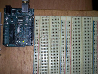 1. Here we have the basic breadboard set up next to the Arduino. Note the way that the breadboard is structured - the vertical blue and red columns are electrically linked as long, single lines, and the horizontal half-rows of five points are electrically linked.
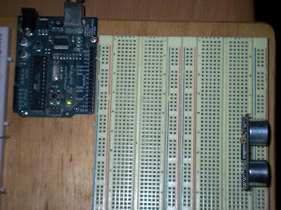 2. Place the Ping))) sensor onto the breadboard. Note that the sensor has three pins. When looking at the front of the sensor, these three pins are marked GND (ground), 5V (the power supply) and SIG (the data signal pin).
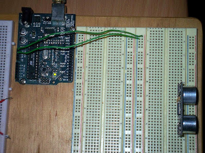 3. Set up the power bussing for the breadboard. Make a connection between the 5V pin on the Arduino board and the red vertical line. The red vertical line is now the supply voltage bus. Make a connection between the GND pin on the Arduino board and the blue vertical line. The blue vertical line is now the ground bus.
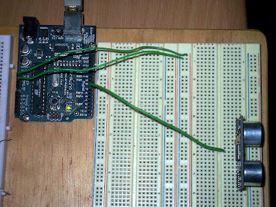 4. Connect the data signal (marked SIG) pin of the PING))) sensor to digital pin 7 of the Arduino board.
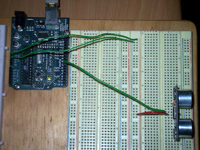 5. Connect the power supply pin (marked 5V) of the PING))) sensor to the red vertical line (the power supply bus).
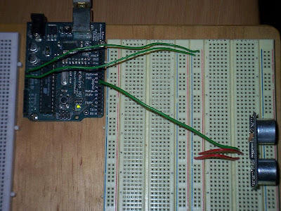 6. Connect the ground pin (marked GND) of the PING))) sensor to the blue vertical line (the ground bus).
Software Setup
The software setup is made up of three main parts:
A) Upload the sketch to the Arduino board (this only has to be done once).
B) Open and set up the Max/MSP patch.
C) Connect to your favourite electronic music making / synthesis environment (SuperCollider, Max/MSP, Ableton Live etc).
A) Upload the sketch to the Arduino board.
1) Download the code from here:
http://milkcrate.com.au/_other/downloads/ping/very_simple/
2) Open the Arduino software. Version 010 was used for this demonstration.
3) Paste the code into a new sketch.
4) Verify the code by going to Sketch > Verify.
5) Make sure the Arduino board is connected to the computer.
6) Select the correct serial port by going to Tools > Serial Port. The Arduino should come up as /dev/tty.usbserial-A4---
7) Upload the sketch by going to File > Upload to I/O Board. Depending on the type of Arduino board you have, you might need to physically press the reset button while you execute this command.
8) The RX and TX LED's on the Arduino board should flash, indicating the upload process.
B) Open and set up the Max/MSP patch.
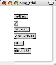
1) Make sure the Ping))) circuit is set up and that the Arduino board is plugged into the host computer.
2) Open up the Max/MSP patch in Max/MSP. The patch can be downloaded here:
http://milkcrate.com.au/_other/downloads/ping/very_simple/
3) You may need to adjust the first argument of the serial object, depending on which serial port your Arduino board connects to your computer. Experiment or use a print message connected to the serial object in order to work out which symbol is which serial port.
4) You may wish to adjust the continuous controller number (the argument of the ctlout object).
C) Connect to your favourite environment
By sending the control data along a virtual MIDI path, you can now send the Ping))) data to may other types of places and control other things.


10 comments:
Awesome:))
)))
Very cool! Thanks for the info too...I used your tutorial here to do the same thing but using Pure-Data instead of Max/MSP. Works great!
hi sebastian i've been trying to adapt some code so i can get two ping sensors to work on one board and output the data to max/msp here's what i've got so far:
http://mouldywashingmachine.blogspot.com/2009/01/ping-post.html
i have two different codes that don't quite work the way i want them to, can you have a look please?
Hi Sebastian,
The info was really useful for my project.
I was wondering if you have any way to transform the values from the ping to centimeters?
Thank you very much!!
Best
Hi Sebastian,
thank you for your code - I have recently acquired a Ping ))) sensor and have been trying to get your code to work but sadly with no luck, when I paste it into the arduino window i get the following error message;
/tmp/build30952.tmp/core.a(wiring_serial.c.o): In function `__vector_18':
/Applications/arduino-0015/hardware/cores/arduino/wiring_serial.c:112: multiple definition of `__vector_18'
/tmp/build30952.tmp/core.a(HardwareSerial.cpp.o):/Applications/arduino-0015/hardware/cores/arduino/HardwareSerial.cpp:95: first defined here
Couldn't determine program size: hardware/tools/avr/bin/avr-size: '/tmp/build30952.tmp/Serial_to_Midi.hex': No such file
do you know what might be the problem?
Very nice! Made a small change in the following:
beginSerial(9600); to Serial.begin(9600). Works fine now!
(Macbook - Leopard - Arduino16)
Thanks alot for posting your project and findings! Very interesting and well constructed stuff :D
I was just wondering if you would mind giving me a few bits of advice...I am attempting to do a very similar project but using a Sharp infra-red sensor instead of a PING sensor.
So far I have been able to successfully connect the sensor with my arduino by using this following code:
int var1 = 0;
void setup() {
Serial.begin(9600);
}
void loop(){
var1 = analogRead(0);
Serial.print(var1);
Serial.println();
delay(1000);
}
I used this code to see if the sensor was working and used the serial monitor which showed that the sensor was indeed communicating the Arduino because a new line of code was being written as I moved my hand in front of the IR sensor - with the number changing depending how close or far away from the sensor my hand was.
What I am wondering now is - is there a way I can borrow from/modify the code you have used to convert the PING into Arduino information so that I can convert the output of my IR sensor into MIDI?
My main goal is to convert the output of my IR sensor to MIDI via the arduino, and send this to MAX/MSP to then be sent to Reason/Ableton etc to be used as a MIDI controller
Thanks alot mate :) ...much appreciated!
when i change "serial a" to "COM3" it crashes, can you maybe explain what is going wrong?
to The Rhythmist ;
just wondering how you got this working in pd? got it working in max/msp but my trial of this runs out tomorrow - tried to sort it in pd but just can't get it to read the ping. was wondering could you share the patch or some advice?
cheers
Harry laughter
Post a Comment