Wednesday, June 25, 2025
Sunday, June 22, 2025
Generating a 360 Video from Still Image and 4ch Ambisonics File
Create a video from a still image. Combine the video created in the previous step with 4 channel audio. Inject the correct 360 metadata into the video created in the previous step. Requires ffmpg and spatial-media.
Download example gradient here:
https://universityofadelaide.box.com/s/q8g5f31kw5iabtishv4sg93zag2ltgzh
Download short ambix wav file here:
https://universityofadelaide.box.com/s/qrrd87dztepn4lxi3uv7m1wyj3zvgkn6
ffmpeg -loop 1 -i [input image file] -t 8 -vf format=yuv420p -c:v libx264 [output video file 1]
ffmpeg -i [input video file 1] -i [input ambisonics audio file] -c:v copy -c:a pcm_s24le -map 0:v:0 -map 1:a:0 [output video file 2]
python spatialmedia -i -a [output video file 1] [output video file 3]
Monday, June 02, 2025
xNT Hand Implant to Webhook to Home Assistant Event Trigger
https://www.instagram.com/p/DKZQHQBi4Eq/
Sunday, June 01, 2025
Teensy Basics: Distance Sensing with VL53L0X Laser Sensor
Overview
The VL53L0X is a ranging sensor that uses time-of-flight of a laser to determine the distance to the next surface correct to the mm with a maximum of 2m. The sensor uses an i2c interface with a default address of 0x29. The xshut pin allows for address control and start up / shut down during setup.
Hardware Setup
Here are the pinouts for the Teensy 4.1 and the VL53L0X:
Make the following connections between the Teensy 4.1 and the sensor:
- Teensy GND to VL53L0X GND
- Teensy 3v3 to VL53L0X VIN
- Teensy pin 0 to VL53L0X XSHUT
- VL53L0X unconnected
- Teensy pin 18 to VL53L0X SDA
- Teensy pin 19 to VL53L0X SCL
No other passive components are required.
Software setup
This sensor example requires the Pololu vl53l0x library, which is available from the Arduino library manager.
Example: Reading distance and printing to the serial monitor
Saturday, April 26, 2025
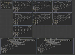
Max Gen Filter Cookbook

256 tap manual finite response filter
https://github.com/little-scale/littlescale-max-patches/blob/master/manual_fir_filter.maxpat
Morphing-type biquad filter
https://github.com/little-scale/littlescale-max-patches/blob/master/biquad_testing.maxpat
https://github.com/little-scale/littlescale-max-patches/blob/master/biquad-full-basic.gendsp

12 stage biquad lowpass with outputs at 12, 48, 96 and 144 db per octave
https://github.com/little-scale/littlescale-max-patches/blob/master/duodecim-biquad.maxpat
https://github.com/little-scale/littlescale-max-patches/blob/master/duodecim-biquad.gendsp
50 stage single pole lowpass
https://github.com/little-scale/littlescale-max-patches/blob/master/singlepole-cascading.maxpat
https://github.com/little-scale/littlescale-max-patches/blob/master/singlepole.gendsp
https://github.com/little-scale/littlescale-max-patches/blob/master/singlepole.maxpat
Basic biquad implementation of lpf, hpf, bpf, notch, all, shelves in one gen~ patch
https://github.com/little-scale/littlescale-max-patches/blob/master/biquad-full-basic.maxpat
https://github.com/little-scale/littlescale-max-patches/blob/master/biquad-full-basic.gendsp
Moog-style ladder filter with resonance and saturation
https://github.com/little-scale/littlescale-max-patches/blob/master/ladder-filter.maxpat
https://github.com/little-scale/littlescale-max-patches/blob/master/ladder-filter.gendsp
Harmonic resonant bandpass bank with 16 partials and controls for central partial and gain spread.
https://github.com/little-scale/littlescale-max-patches/blob/master/reson-bpf-harmonic-bank.maxpat
https://github.com/little-scale/littlescale-max-patches/blob/master/reson-bpf-harmonic-bank.gendsp
Resonant bandpass filter
https://github.com/little-scale/littlescale-max-patches/blob/master/reson-bpf.maxpat
https://github.com/little-scale/littlescale-max-patches/blob/master/reson-bpf.gendsp
%20filter%20with%20LFO%20modulation.jpeg)
Third order (3ff / 3fb) filter with LFO modulation across all co-efficients
https://github.com/little-scale/littlescale-max-patches/blob/master/filter-3ff-3fb.maxpat


