Here is a Sega Master System 2 "prosound" -- that is, taking the sound directly from the VDP chip, which contains the integrated SN76489 clone. The VDP that is found in the Australian PAL SMS2 is the 315-5246.
Normally, the only way to get sound out of the Sega Master System 2 is via a television set, a VCR or a dedicated RF demodulator. The sound quality of course suffers (as well as the picture quality) and also it is quite an inconvenience, making the console unusable for live use in music concerts and recording etc.
This tutorial will concentrate on the audio side of things, because as we all know audio is more important than visuals (at least as far as this blog is concerned). If you are wanting to get composite or RGB video output from your SMS2, this is not the place.
The Master System 1 does have a (more) direct audio output, but it is also much bulkier than an SMS 2. By adding a direct audio line out, the SMS2 is turned into a gig-worthy machine, and travels well due to its smaller size.
The resulting output sounds very nice indeed.
Step-by-step
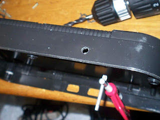 1. Take your SMS2 apart. First, remove the base screws and take off the top half of the plastic case. Next, remove the screws holding the top of the metal shield in place. Finally, remove the two black screws that hold the cartridge port and PCB in place. Remove the console from the case completely. Drill a hole with a suitable size in the bottom half of the SMS2 case. there is plenty of room, so you have a few options of where to put the hole.
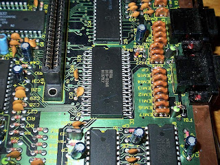 2. Locate the VDP chip, labeled SEGA 315-5246. It is the only chip with alternating long and short legs. Locate pin 15. The pin directly to the left of the indent and the black circle is pin 1, so you need to count down 15 pins.
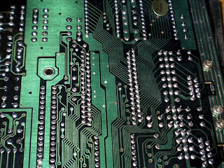 3. Turn the PCB around and locate pin 15 again, keeping in mind that the pins are mirrored because you are essentially looking at the back of the chip.
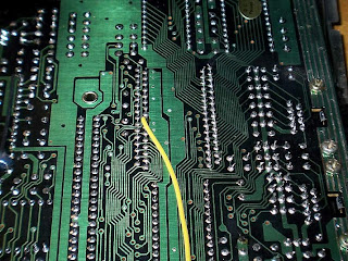 4. Solder a wire to pin 15. This is the audio signal cable. The way I approach these sorts of things is by first adding a bit of solder to the point, and then heating up that point again and sticking the wire into the blob of solder. This technique works okay if one has done it more than once. After having soldered the connection, I added some hot glue to keep the wire in place and add some strain relief (although this is not necessary).
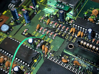 5. Locate a ground point on the PCB. There are many points that are suitable, but I have chosen the grounded leg of a resistor, R14 to be exact. Solder a wire to the ground point that has been chosen.
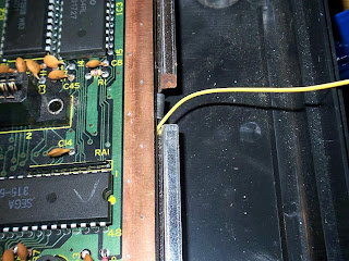 6. Start putting the SMS2 back together, by placing the PCB back onto the bottom of the shield. I found a point on the right hand side where I could snake out my audio signal wire without fear that it would get squashed.
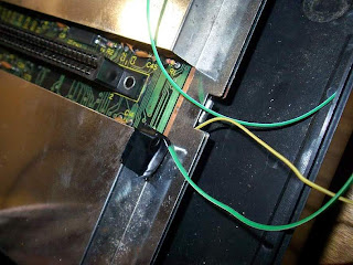 7. Replace the top side of the shield and find a point to snake out the ground wire from the PCB. I just used the same are where the cartridge goes in (which is much larger than it needs to be, really) and I used a little bit of tape to secure the wire.
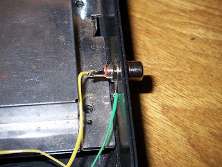 8. Solder your audio connection together. I used an RCA plug. The wire coming from the VDP chip pin 15 is the audio signal and the wire coming from the grounding point on the PCB is ground.
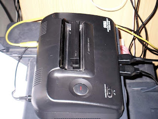 9. Reassemble the casing for the SMS2. You're ready to rock!


9 comments:
Wouldn't the quality be better if you lifted the pin instead of leaving it connected? Also, why not just use the huge ground plane on the edge of the board?
Hi Maxim,
I hadn't thought of lifting the pin, I will have to give it a try. The sound quality is actually already relatively good, though, but of course everything can always be improved.
In terms of the ground plate -- I just found it easier to solder to a direct point, but I guess everyone has their own way of doing things :)
On the third picture from the top you have something lying on the mobo that looks like a coin with a smiley on it. WTF is that?
lol, click on the photo Nitro! It's a "Q.C. passed" sticker! :D
You can also solder onto the negative pin of capacitor C31, which I found out from this page: http://www.smspower.org/dev/docs/wiki/HardwareHacks/VideoOutput
The key paragraph being "Audio is obtained from pin 15 of the SMS's custom chip marked 315-5246, which has 64 pins close together in a zig-zag formation. (Rather than solder directly to the chip, you can instead solder to the negative leg of capacitor C31, an electrolytic capacitor just in front of the CXA 1145.)". Might help someone looking into doing this hack :-)
@ Paul: Thanks for the tip! Much appreciated. I'll keep that in mind for my next line out mod :)
Isn't that R14 pin connected to +5V ?
I don't have my SMS2 boards with me right now, but I don't understand why it wouldn't be connected to the ground plane we see on the picture, like R20 ? (C42's negative pin is connected to it, so it's a ground plane for sure).
Isn't R14 connected to +5V ?
The resistor in the exact same place (VDP color output pull up) on my SMS2 is connected to +5V.
Post a Comment