Showing posts with label teensy basics. Show all posts

Sunday, June 01, 2025

Teensy Basics: Distance Sensing with VL53L0X Laser Sensor

Overview

The VL53L0X is a ranging sensor that uses time-of-flight of a laser to determine the distance to the next surface correct to the mm with a maximum of 2m. The sensor uses an i2c interface with a default address of 0x29. The xshut pin allows for address control and start up / shut down during setup. 


Hardware Setup

Here are the pinouts for the Teensy 4.1 and the VL53L0X: 


Make the following connections between the Teensy 4.1 and the sensor: 

  • Teensy GND to VL53L0X GND
  • Teensy 3v3 to VL53L0X VIN
  • Teensy pin 0 to VL53L0X XSHUT
  • VL53L0X unconnected
  • Teensy pin 18 to VL53L0X SDA
  • Teensy pin 19 to VL53L0X SCL

No other passive components are required. 


Software setup

This sensor example requires the Pololu vl53l0x library, which is available from the Arduino library manager. 


Example: Reading distance and printing to the serial monitor

#include <Wire.h>
#include <VL53L0X.h>

VL53L0X sensor;

// XSHUT pin for VL53L0X
const int XSHUT_PIN = 0;

void setup() {
Serial.begin(115200);
Wire.begin(); // SDA = 18, SCL = 19 on Teensy 4.1
delay(100);

// Initialize XSHUT pin
pinMode(XSHUT_PIN, OUTPUT);
digitalWrite(XSHUT_PIN, LOW); // Reset sensor
delay(10);
digitalWrite(XSHUT_PIN, HIGH); // Power up sensor
delay(10);

// Initialize VL53L0X
sensor.setTimeout(500);
if (!sensor.init()) {
Serial.println("Failed to detect VL53L0X.");
while (1);
}

sensor.startContinuous();
Serial.println("VL53L0X started.");
}

void loop() {
uint16_t distance = sensor.readRangeContinuousMillimeters();

Serial.print("Distance: ");
Serial.print(distance);
Serial.println(" mm");

if (sensor.timeoutOccurred()) {
Serial.println("TIMEOUT");
}

delay(20);
}

Wednesday, June 03, 2020

Teensy 3.6 with HC-SR04 Distance Sensor

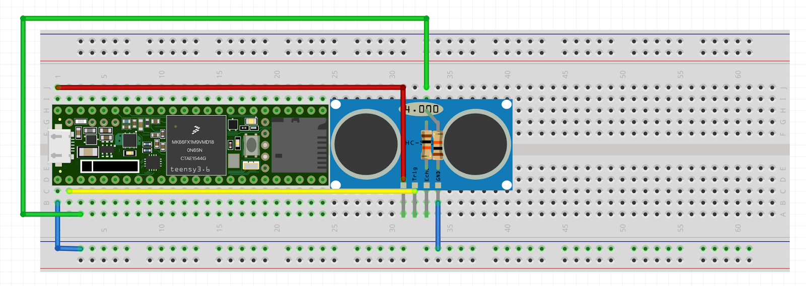
The HC-SR04 is a low-cost ultrasonic sensor that uses two transducers to measure the distance in front before being blocked by an object or surface. The sensor has four pins GND, VCC, TRIG and ECHO.


Hardware Setup

  • HC-SR04 Ground should be connected to Teensy 3.6 ground. 
  • HC-SR04 VCC should be connected to Vin (which should output 5V if connected to USB). 
  • HC-SR04 TRIG should be connected to Teensy 3.6 digital pin 0. 
  • HC-SR04 ECHO should be connected to one leg of a resistor (1k to 100k). The other leg of the resistor should be connected to Teensy 3.6 digital pin 1. The other leg of the resistor should also be connected to one leg of a second resistor (1k to 100k - same value as the first resistor). The other leg of the second resistor should be connected to ground. 
  • These resistors going to ground and pin 1 form a voltage divider that takes the output voltage from the HC-SR04 from 5V to 2.5V, which is suitable for the Teensy 3.6. 
Here is a photo and layout for the breadboard with and without the sensor connected. Note the connections for the resistors, ground, and digital pins. 


Example 1 - Serial Output

These examples use the HCSR04 library by Martin Sosic, which can be downloaded via the Library Manager tool in Arduino. 

The Arduino Serial monitor will output the measurement as a distance in cm. 


Example 2 - USB MIDI CC

The distance sensor is scaled to a suitable range of 0 - 127 and sent over USB as MIDI CC values, that can be used in Ableton Live and other software to control sound and music parameters.


View the code here: https://github.com/little-scale/arduino-sketches/blob/master/Distance_Sensor_HCSR04_2_USB_MIDI_CC.ino


Example 3 - USB MIDI Pitch with Note On via Push Button

A button is added to the setup, connected to Teensy 3.6 digital pin 32. Pressing the button generates a note on event that uses the distance sensor to set the pitch of the note. Depressing the button generates a note off event.


View the code here: https://github.com/little-scale/arduino-sketches/blob/master/Distance_Sensor_HCSR04_3_USB_MIDI_Pitch.ino


Wednesday, May 15, 2013

Teensy Basics 6: R2R DAC Primer

Overview
This article assumes that you have read Teensy Basics 1 and Teensy Basics 2 and Teensy Basics 3 and Teensy Basics 4 and Teensy Basics 5.

It is easy to build a simple DAC that can be used with the Teensy. Using port manipulation, it is also possible to program data for the DAC.


R2R DAC
We can use port manipulation to help with creating and controlling a DAC. A DAC is an digital to analog converter. It is a circuit or device that can take a digital control (i.e. discrete data or number in some form) as an input. The output is an analog voltage the corresponds to the value received.

A DAC can be used to generate audio and control waveforms. An example of a very simple, easy to build DAC is called an R2R ladder DAC. R2R = “resistance, 2 x resistance” because only two different values of resistors are needed.


Hardware Setup
The following is a diagram of an 8bit R2R ladder DAC. Every horizontal resistor should be “2R” e.g. 20K. Every vertical resistor should be “R” e.g. 10k. Each bit (0 – 7) is a digital connection, and is either HIGH or LOW.


Consider the Teensy input / output pins in terms of ports in conjunction with the above diagram:


We can then connect the DAC to the Teensy to the DAC in the following way:


Here is an example of a breadboard setup. The output (which is the blue line without a connection) should be connected to the signal of an audio input of a speaker system. The ground of the Teensy should be connected to the ground of an audio input of a speaker system.


Writing code for the DAC
The concept of how to program is straightforward. A value is written to the port. That value is converted to an analog voltage by the R2R ladder DAC. Each value is an instantaneous sample. Therefore, we need to be constantly writing new values to the DAC in order to generate a changing waveform. 

A value of 0 that is written to the DAC will result in an output of 0V. The maximum value allowed by the bit depth (15 if it is a 4-bit DAC, 255 if it is an 8-bit DAC) will result in an output of approximately 5V. Intermediate values are scaled accordingly. The bit depth will determine what voltage output is of a corresponding data input.

e.g.

The DAC is 8bit (i.e. 0 – 255): 
A value of 0 = 0 / 255 = 0V
A value of 15 = 15 / 255 = 0.059 V

The DAC is 4 bit (i.e. 0 – 15):
A value of 0 = 0 / 15 = 0V
A value of 15 = 15 / 15 = 5V

The DAC can be programmed very easily. First, we need to set the direction of the pins to output in the setup() function: 


Then, it is simply a matter of looping code and telling the DAC what to do. For example, the following generates a square wave.


The following generates a sawtooth wave. 

The following generates a noise wave. 
The following generates a sine wave. 


Conclusion
The aim of this article is to provide a foundation for a DAC upon which can be built. Be aware that more complex code is needed to more complex sound, and that an output buffer is useful for many audio applications.

Teensy Basics 5: Port Manipulation

Overview
This article assumes that you have read Teensy Basics 1 and Teensy Basics 2 and Teensy Basics 3 and Teensy Basics 4.

Port manipulation with the Teensy allows the code to read, write and set the direction of up to 8 digital pins at once using low-level instructions. Port manipulation is useful for optimising code and for instantaneously setting multiple pins or receiving data from multiple digital pins.


Considering the Teensy Pinout
To understand port manipulation, an understanding of binary notation is useful.

Binary notation represents numbers with either a 0 or a 1 per digit. With microcontrollers, it is sometimes very useful to think in terms of binary notation for specific tasks:
- Interfacing with groups of pins
- Dealing with certain kinds of maths (bitwise operators)


Each additional bit that we can use to represent a given number increases the range of numbers that we can represent, as follows:

1 bit = 2^1 = 0 – 1 = X
2 bits = 2^2 = 0 – 3 = XX
3 bits = 2^3 = 0 – 7 = XXX
4 bits = 2^4 = 0 – 15 = XXXX
5 bits = 2^5 = 0 – 31 = XXXXX
6 bits = 2 ^6 = 0 – 63 = XXXXXX
7 bits = 2^ 7 = 0 – 127 = XXXXXXX
8 bits = 2^8 = 0 – 255 = XXXXXXXX

Binary notation can be used in Teensy / Arduino by using the prefix 'B'.

e.g. B11111111 = 255
e.g. B00001111 = 15
e.g. B00000111 = 7
e.g. B10011010 = 154
e.g. B01111111 = 127


Port manipulation refers to dealing with groups of pins at once. Port manipulation allows the program to read or write groups of digital pins simultaneously without needing to using multiple digitalWrite() or digitalRead() commands.

The Teensy has a number of ports, namely PORTB, PORTD, PORTC and PORTF. Each port is made up of up to eight pins. Every input or output on the Teensy is part of a port.

Normally - when addressing individual digital pins in the Arduino IDE - it is sufficient to think about Teensy as having a pinout as follows:


However, we can also consider the Teensy in terms of ports, as follows:
Every input / output pin is labelled as P something, e.g. PB0, PB1, PB2 etc. This literally means "Port B, pin 0", "Port B, pin 1" etc.

In order to manipulate these ports i.e. these groups of pins, there are specialized functions.

The three port manipulation commands are:
PORTx – “replacement” for digitalWrite()
PINx – “replacement” for digitalRead()
DDRx – “replacement” for pinMode()

PORTx sets the pins of that port to either HIGH (1) or LOW (0) in binary. It is a replacement of using digitalWrite() eight times in a row

e.g.
PORTD = B11111111; // == 255
PORTD = B00000000;  // == 0

PINx reads the value of the the PORT pins in binary. It is a replacement of using digitalRead() eight times in a row

e.g.
 if(PIND == B00000000) {
// do something if no pins are HIGH
}


DDRx sets the direction (input or output) using a binary number. It is a replacement of using pinMode() eight times in a row. A "1" in that bit position will set that pin as an output. A "0" in that bit position will set that pin as an input.

e.g.
 DDRD = B11111111;
// all pins of PORTD as outputs!
 DDRD = B00000000;
// all pins of PORTD as inputs!


Conclusions
Although there are often times when standard digitalWrite and digitalRead can be used, there are times when using port manipulation is extremely useful. Keep this in mind when programming for Teensy and Arduino!

Tuesday, March 19, 2013

Teensy Basics 4: If Statements

Overview
This article assumes that you have read Teensy Basics 1 and Teensy Basics 2 and Teensy Basics 3.

'If statements' are structural functions within a Teensy program that can branch your program to perform varying blocks of code depending on the state of 'something' - a variable, an input pin, whatever.


Usage
For example, maybe you've connected a series of buttons to your Teensy. Perhaps you want a different action to occur whenever you press each of these buttons. You can use If statements to add conditions to your - i.e. whether a given button is pressed or not - and then execute a given action - e.g. turn on an LED, play a sound, send a MIDI Note - if and only if a particular button is pressed.


If statements are powerful and very useful structural components to our code, and the great thing is that - as long as we think about things logically - they are easy to deal with.

If statements use boolean expressions and operators, to make a comparison and determine whether a particular condition is TRUE or FALSE. If it has been determined that a particular condition is TRUE at the time of testing, then a block of code is executed.

The syntax for a single, simple If statement is as follows:
if(value operator value) {
    do code
}


Logical Comparisons
As a concrete example, here is this syntax written in Arduino / Teensy:


This code basically asks the question: Is our pin 0 EQUAL TO 1?

And the response is, if the pin 0 is equal to 1, let's turn the onboard Teensy LED to ON. The following boolean operators to form our logical comparison are possible:

• ==    equals
• !=        does not equal
• > greater than, >= greater than or equal to
• < less than, <= less than or equal to


With this in mind, consider the following four statements. 


• In which cases is the code executed if time_value is equal to 100? Why?
• In which cases is the code executed if time_value is equal to 101? Why?
• In which cases is the code executed if time_value is equal to 99? Why?


IMPORTANT: Do not confuse '==' with '='. The first is a comparison.
e.g. Time_value == 100 is asking the question "does Time_value equal 100?"
whereas the second is setting the value of Time_value
e.g. Time_value = 100 is saying "let Time_value = 100"


Do not confuse these two!


Linking If Statements Together
If statements can be made more complex by adding additional logical components. Boolean expressions link multiple variables together, thereby effectively adding additional conditions that have or might have to become true in order for the If statement to execute its code.

The AND (&&) indicates that BOTH conditions must come TRUE in order for the code to execute, for example:


In this example, time_value must be less than 100 AND digitalRead(10) must equal 1 in order for this IF statement to be TRUE - i.e. both conditions must be true because of the && statement


The OR (||) indicates that EITHER OR condition must come TRUE in order for the code to execute, for example:
In this example, time_value must be less than 100 OR digitalRead(1) must equal 1 in order for this IF statement to be TRUE - i.e. either condition can be true, but both don't have to be true because of the || statement


Using the Else / Else If Statement
The else statement can come after an If statement, and contains code that will execute if the conditions in the original If statement are not TRUE.

If that sounds complex, consider the following sentence.

"I will go to the go to the shop IF it is OPEN, ELSE I will go to the park."

This summarises the link between the IF and ELSE statements quite concisely. In terms of a concrete example in Teensy code, consider the following block:


This is the code equivalent of:
"If button 1 is pressed, turn the LED on, else turn the LED off"


We can further add a logical structure by using an Else If statement, like so:


These are very simple examples of these types of statements, but more complex programming will involve using more complex arrangements of If statements. The basic structure, however, will remain the same.


Nested If Statements
Keep in mind that you can have one If statement located within the code of another If statement - we can nest our If statements within each other.

This is really useful for testing for a number of different types of conditions that should only occur after another condition comes true first.

On a music data level, we might use nested to program a Teensy to react to a certain controller number on a certain controller channel.

For example:


In this case, first we test for MIDI channel 1, followed by controller 1. If it is controller 1, then we do something. If the controller is number 11, however, then we do something else.


Conclusion
With all of these If statements, the key is to 1) think about your problem or outcome that you want your program to achieve 2) develop a logical flow of how to achieve that outcome 3) match up If statements, conditions and comparisons to the appropriate point in the program flow.

If statements are meant to be easy to read - like a sentence - and follow a straightforward logic. Don't be overwhelmed by If statements with multiple parts or an If statement followed by an Else If and then an Else, simply break it down and think about each part individually. 

Teensy Basics 3: Switches and Digital Inputs

Overview
This article assumes that you have read Teensy Basics 1 and Teensy Basics 2.

Buttons and toggles are great ways of setting states so that different things can happen in your program. This post will cover the physical connections of various types of switches and how to read these switches with the Teensy. 


Switch and Button Types
The majority of switches and buttons can be categorised into at least four different, common categories:

• SPST
• SPDT
• DPST
• DPDT

Let's take a look at these four different types. Even though there are different variations on each, the basic concept is described below.

SPST is short for "Single Pole Single Throw". This indicates a very simple button or switch, whereby either a connection is made or is broken, depending on the physical state of the switch. We can represent the SPST switch with the following diagram.


The SPST switch itself has two terminals. In an off state, these terminals are disconnected. In an on state, these terminals are connected.

In an audio context, we can conceptually think of the SPST switch or button as muting or unmuting a mono signal, like so.


SPDT is short for "Single Pole Double Throw". This indicates a switch whereby either a connection is made between points A and B, or a connection is made between points A and C. We can represent the SPDT switch with the following diagram.


The SPDT switch itself has three terminals. In an off state, two terminals are connected (one of them the common) and the remaining terminal is disconnected. In an on state, the previously disconnected terminal is connected to the common, leaving the previously connected terminal disconnected.

In an audio context, we can conceptually think of the SPDT switch or button as a mono signal selection switch, like so. Normally, signal A goes through to the "common" terminal. However if the switch is activated, signal B can now go through to the common terminal instead of signal A.


DPST is short for "Double Pole Single Throw". This indicates a switch whereby either a connection is made or broken between two pairs of terminals.


The DPST switch itself has four terminals. We can think of the DPST switch as simply being two SPST switches that are switched using the same physical mechanism. We can have two signals that go through two pairs of terminals, and either the signal goes through or it doesn't, depending on the physical state of the switching mechanism (which connects or disconnects both pairs of terminals simultaneously).

In an audio context, we can conceptually think of the SPST switch or button as muting or unmuting a stereo signal, like so.


DPST is short for "Double Pole Double Throw". This indicates a switch whereby either a connection is made between points A and B AS WELL AS D and E, or a connection is made between points A and C AS WELL AS points D and E. We can represent the DPDT switch with the following diagram. 


The DPDT switch itself has six terminals - two lots of three. We can think of the DPDT switch as simply being two SPDT switches that are switched using the same physical mechanism.  In an off state, two terminals in each lot of three are connected (one of them the common) and the remaining terminal is disconnected. In an on state, the previously disconnected terminal is connected to the common in each lot of three, leaving the previously connected terminal disconnected. 

In an audio context, we can conceptually think of the DPDT switch or button as a stereo signal selection switch, like so. Normally, signals A.L and A.R go through to the "common" terminals. However if the switch is activated, signals B.L and B.R can now go through to the common terminals instead of signal A.L and A.R.


Connecting Switches or Buttons to Teensy
The most common switches and button types that you will connect to a Teensy are SPST and SPDT. The connections for both are as follows.

An SPST switch connection is summarised with this diagram. 

• Connect 5V to one terminal of the switch
• Connect the other terminal of the switch to a Teensy digital pin
• Also connect the other connection of switch to one leg of 10k – 100k resistor
• Connect the other leg of resistor to ground


When button is not pressed, the Teensy input pin is connected to ground via the 10K resistor
When button is pressed, the Teensy input pin is connected to 5V, as this provides the path of least resistance.

A resistor that is used in this way is called a “pull down resistor”, because it pulls the Teensy digital signal down to ground if the button is not pressed. If this resistor was not in the circuit, the Teensy digital pin would not be connected to anything whenever the button is not pressed, leaving the pin 'floating' – this would result in noise, as the pin randomly oscillates between LOW and HIGH.


A SPDT switch connection is summarised with this diagram.

• Connect 5V to an outside terminal of the switch
• Connect ground to the other outside terminal of the switch
• Connect a Teensy digital pin to the common terminal of the switch (most often this is physically the middle terminal)

When the switch is “off”, the common terminal (and thus the Teensy pin) is connected to ground. When the switch is “on”, the common terminal (and thus the Teensy pin) is connected to 5V.

• Connect one or more switches to Teensy following the above instructions


Voltage Thresholds
The digital pins of the Teensy can act as inputs or outputs. When acting as inputs, the pins are either HIGH or LOW (1 or 0), depending on the voltage applied to them. The Teensy has a voltage threshold to trigger the transition from 0 to 1 and 1 to 0.

This threshold voltage is not 2.5V (i.e. half of 5V) as might be expected. Instead, this threshold voltage is between 1.1V and 1.7V depending on the power supply voltage of the Teensy, which is normally from around 3V to a maximum of 5.5V.

Of interest might be these "voltage thresholds" that trigger a LOW to HIGH transition or a HIGH to LOW transition.

The following graph shows the voltage thresholds for a LOW to HIGH transition:
The following graph shows the voltage thresholds for a HIGH to LOW transition:
• Though this section may seem irrelevant, there may be more complex digital circuits where this information will come in handy!


Reading A Switch in Teensy
To read a switch or button, we need to use set the relevant digital pin of the Teensy to be an input, like so:


The function digitalRead( ) with an argument of the pin number to read will return the value (0 or 1 for LOW or HIGH - or ground or 5V) of that particular digital pin. This returned value can be stored in a variable or used in another function.


We can use this function to read the value of pin 0 into a variable, like so:


And then, we can use that variable to actually do something with the state of our digital pin, whose state is set by the physical button or switch. The code below turns on the onboard Teensy LED (which is found on digital pin 11) whenever the button is pressed or the switch is turned on.