This is a follow-on from the previous post, and shows how to send PING))) ultrasonic sensor data via MIDI continuous controller messages, avoiding the use of Max/MSP or any other intermediate software layer. Of course, this requires a MIDI to USB or similar hardware interface.
The Arduino board and PING))) sensor still require a power source. This can be via the USB cable (as in this example) or potentially a mains AC/DC transformer or a suitable battery.
Hardware Connections
You will need• 1 x PING))) sensor
• 1 x Arduino board
• A breadboard
• Some jumper wires
• A USB A to B cable
• A 220Ω resistor
• Three alligator clips
• A 5 pin DIN connector
Please note that an older NG board was used in this demonstration, but a Diecimilia board etc. should of course be fine as well.
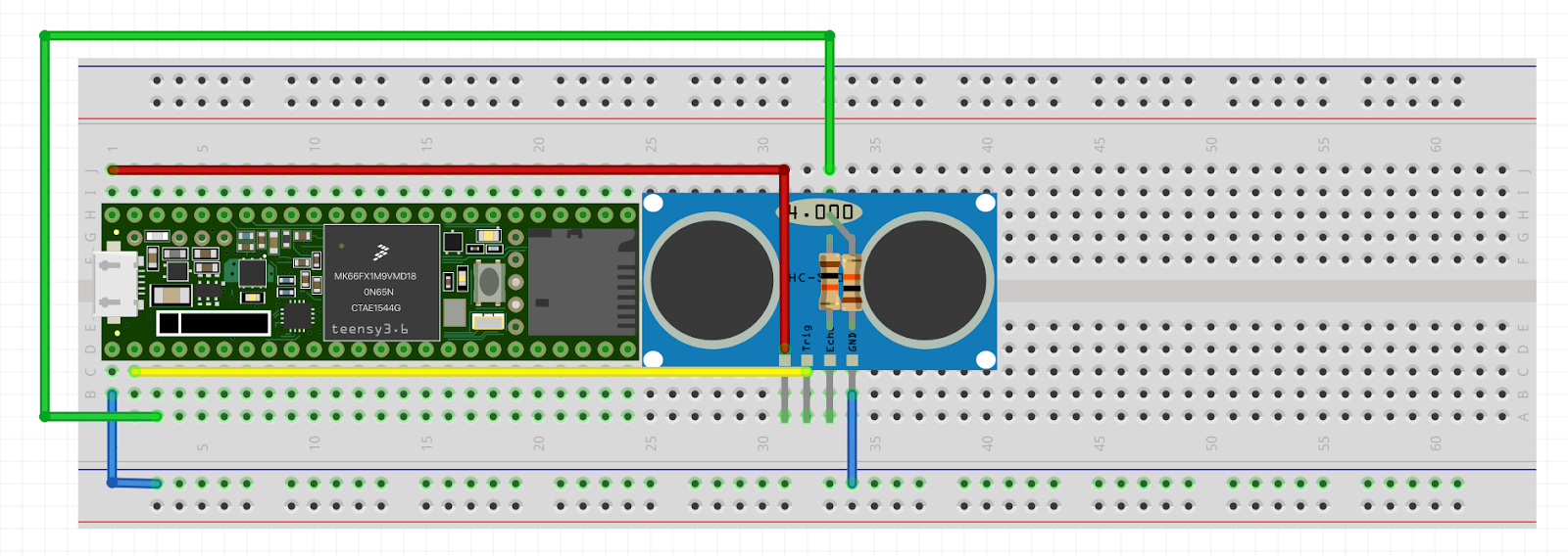
Breadboarding the Circuit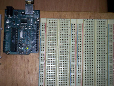
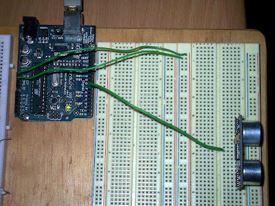
1. Here we have the basic breadboard set up next to the Arduino. Note the way that the breadboard is structured - the vertical blue and red columns are electrically linked as long, single lines, and the horizontal half-rows of five points are electrically linked.
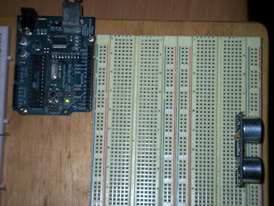
2. Place the Ping))) sensor onto the breadboard. Note that the sensor has three pins. When looking at the front of the sensor, these three pins are marked GND (ground), 5V (the power supply) and SIG (the data signal pin).
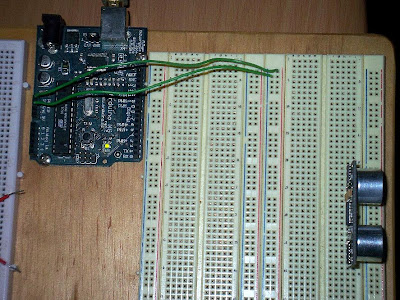
3. Set up the power bussing for the breadboard. Make a connection between the 5V pin on the Arduino board and the red vertical line. The red vertical line is now the supply voltage bus. Make a connection between the GND pin on the Arduino board and the blue vertical line. The blue vertical line is now the ground bus.
4. Connect the data signal (marked SIG) pin of the PING))) sensor to digital pin 7 of the Arduino board.
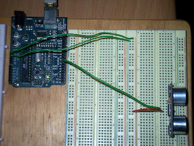
5. Connect the power supply pin (marked 5V) of the PING))) sensor to the red vertical line (the power supply bus).
6. Connect the ground pin (marked GND) of the PING))) sensor to the blue vertical line (the ground bus).

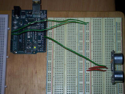
7. Connect one of the 220Ω resistor to the red vertical line (the power supply bus). The 220Ω resistor used in this example had a rating of 5% and 0.25W. However, other resistors with different ratings (for example 2% or 1% tolerance etc) are suitable.

8. Connect one end of an alligator lead (red) to pin 4 of the 5 pin DIN connector.

8. Connect the other end of the alligator lead (red) to the other leg of the 220Ω resistor.

9. Connect one end of an alligator lead (yellow) to pin 5 of the 5 pin DIN connector.

10. Connect the other end of the alligator lead (yellow) to the TX pin (digital pin 1) of the Arduino board).

11. Connect one end of an alligator lead (green) to pin 2 of the 5 pin DIN connector.

12. Connect the other end of the alligator lead (green) to the blue vertical line (the ground bus).
Software SetupUpload the sketch to the Arduino board1) Download the code from here:
http://milkcrate.com.au/_other/downloads/ping/MIDI_output/2) Open the Arduino software. Version 010 was used for this demonstration.
3) Paste the code into a new sketch.
4) Verify the code by going to Sketch > Verify.
5) Make sure the Arduino board is connected to the computer.
6) Select the correct serial port by going to Tools > Serial Port. The Arduino should come up as /dev/tty.usbserial-A4---
7) Upload the sketch by going to File > Upload to I/O Board. Depending on the type of Arduino board you have, you might need to physically press the reset button while you execute this command.
8) The RX and TX LED's on the Arduino board should flash, indicating the upload process.
Editing the Arduino Code (if Needed)
The three most important variables are the first three defined in the sketch, namely:
• delay_time (int)
• MIDI_channel (byte)
• cc_number (byte)
delay_time sets the length of delay (in ms) between successive read/write cycles. The default is 40 ms. MIDI_channel is the channel (1 - 16) to send the MIDI data on. cc_number is the MIDI continuous controller number (0 - 127) to send the MIDI data on. The default MIDI setup is MIDI channel 1 and controller number 127.
You may wish to edit these values to suite your purposes.
Read the MIDI DataSetup your environment to read MIDI continuous controller messages on the interface, channel and cc number as dictated by your setup. The closer an object is to the PING))), the lower the MIDI cc data.
Like so...