Showing posts with label sega mega drive / genesis. Show all posts
Showing posts with label sega mega drive / genesis. Show all posts
Tuesday, October 27, 2015


Friday, May 01, 2015
Friday, May 03, 2013
GenMDM Version 2 PCB 5V Jumper Function
The GenMDM Version 2 PCB contains two main changes to the hardware compared with the Version 1 PCB. These changes are:
• A 5 pin DIN MIDI input connection with associated optocoupler and components
• A 5 volt jumper
The function of the jumper is as follows.
 When the jumper is connected, as shows in the photo above, then the SEGA console will power the GenMDM hardware including the 5 pin DIN MIDI input connection.
Use this jumper in the connected position when using the GenMDM with a traditional 5 pin DIN connection. Do not use this jumper in the connected position when using the GenMDM with a USB cable at all. Never connect a USB cable to the GenMDM unit when the jumper is in the connected position. Doing so may damage the GenMDM.
 When the jumper is disconnected, as shows in the photo above, then USB cable will power the GenMDM hardware. The 5 pin DIN MIDI input connection will not be powered, and a traditional 5 pin DIN connection will not work.
Use this jumper in the connected position when using the GenMDM with a USB cable for MIDI data or for firmware updates. This will provide 5V to the GenMDM hardware via the USB cable.
• A 5 pin DIN MIDI input connection with associated optocoupler and components
• A 5 volt jumper
The function of the jumper is as follows.

Use this jumper in the connected position when using the GenMDM with a traditional 5 pin DIN connection. Do not use this jumper in the connected position when using the GenMDM with a USB cable at all. Never connect a USB cable to the GenMDM unit when the jumper is in the connected position. Doing so may damage the GenMDM.

Use this jumper in the connected position when using the GenMDM with a USB cable for MIDI data or for firmware updates. This will provide 5V to the GenMDM hardware via the USB cable.
Sunday, March 31, 2013
GenMDM PCB Version 1 Modification: SEGA Console Power
The GenMDM interface version 1 PCB can be powered from the SEGA console by performing this simple modification.
This modification will reduce noise in the audio output of the SEGA console, but it will also render the Teensy microcontroller board unable to be powered via USB cable alone.
This may make it unsuitable for people that wish to use their GenMDM Teensy boards for other things.

Take a GenMDM version 1 PCB.

Solder a wire to pin 5 of the 9-pin connector.

Solder the other end of the wire to the VCC pin header of the Teensy socket

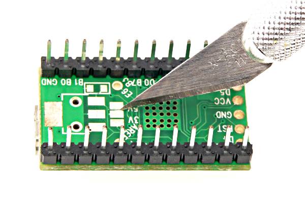
Take your GenMDM Teensy. Note the underside. There is a series of three pads marked 3V 5V. Cut the trace that is between the middle pad and the pad next to the 5V sign. A clear diagram is given here.

This is the Teensy after the trace has been cut. Ensure that there is not connection between the two pads by using a multimeter to check resistance (or lack thereof).
 Insert the Teensy board back into the cradle.
This modification will reduce noise in the audio output of the SEGA console, but it will also render the Teensy microcontroller board unable to be powered via USB cable alone.
This may make it unsuitable for people that wish to use their GenMDM Teensy boards for other things.

Take a GenMDM version 1 PCB.

Solder a wire to pin 5 of the 9-pin connector.

Solder the other end of the wire to the VCC pin header of the Teensy socket

Take your GenMDM Teensy. Note the underside. There is a series of three pads marked 3V 5V. Cut the trace that is between the middle pad and the pad next to the 5V sign. A clear diagram is given here.

This is the Teensy after the trace has been cut. Ensure that there is not connection between the two pads by using a multimeter to check resistance (or lack thereof).

Wednesday, March 27, 2013

Wednesday, February 06, 2013
Proof of Concept: VGM PSG to GenMDM Streaming
This is a proof of concept, whereby a Max patch streams SN76489 PSG data from a .VGM data file to GenMDM and a SEGA in real time.
Sunday, February 03, 2013
SEGA Genesis / Mega Drive YM2612 Register 2C "Loud Samples" Mode Demo
By switching a bit in register 2C of the YM2612 FM sound chip, samples are automatically boosted in amplitude by a massive amount. Below is an example video:
GenMDM v102 and above can access this register on MIDI channels 1 - 6 on CC 97. All distortion is created on the output of the SEGA console, as my sound card was not distorting.
GenMDM v102 and above can access this register on MIDI channels 1 - 6 on CC 97. All distortion is created on the output of the SEGA console, as my sound card was not distorting.
Saturday, February 02, 2013
All SEGA Genesis / Mega Drive TFI Instruments with Friendly Filenames
Download all SEGA Genesis / Mega Drive TFI instruments with friendly names here: http://little-scale.com/GENMDM/TFI_SEGA_INSTRUMENTS/TFI_WITH_FRIENDLY_NAMES.zip . Many thanks to Chipmusic.org user Robugaa for importing and converting these files from the .OPM files.
GenMDM M4L Tools Updated - Now Includes TFI and TFI Folder Import!

The FM editor for GenMDM M4L Tools has been updated to include TFI import and TFI folder import. A TFI file is an FM instrument file from TFM Music Maker. Each TFI file is a single FM instrument. The "TFI" button imports a single TFI file.
The "TFI F" button imports up to 128 instruments from a folder containing 128 or less TFI files - e.g. a SEGA Genesis / Mega Drive instrument settings dump. These instruments are imported into the patch instrument menu. See below for usage examples!
Download all SEGA Genesis / Mega Drive TFI instruments with friendly names here: http://little-scale.com/GENMDM/TFI_SEGA_INSTRUMENTS/TFI_WITH_FRIENDLY_NAMES.zip . Many thanks to Chipmusic.org user Robugaa for importing and converting these files from the .OPM files.
Example of importing a single TFI instrument file:
Example of importing a folder full of TFI instrument files:
.GENM File Format: GenMDM Instrument Patch File Specifications


A .GENM file is used to store GenMDM patch files.
Each patch file can store up to 128 different instrument settings for an FM channel of a GenMDM interface.
A .GENM file is in a standard text format.
Each instrument is stored in the following way:
[Instrument Index], [Algorithm] [LFO FM] [LFO AM] [FM Feedback] [Panning] [OP1 Level] [OP2 Level] [OP3 Level] [OP4 Level] [OP1 Detune] [OP2 Detune] [OP3 Detune] [OP4 Detune] [OP1 Attack] [OP2 Attack] [OP3 Attack] [OP4 Attack] [OP1 Decay 1] [OP2 Decay 1] [OP3 Decay 1] [OP4 Decay 1] [OP1 Decay 2] [OP2 Decay 2] [OP3 Decay 2] [OP4 Decay 2] [OP1 Mul] [OP2 Mul] [OP3 Mul] [OP4 Mul] [OP1 Rate Scaling] [OP2 Rate Scaling] [OP3 Rate Scaling] [OP4 Rate Scaling] [OP1 Amp2] [OP2 Amp2] [OP3 Amp2] [OP4 Amp2] [OP1 Release] [OP2 Release] [OP3 Release] [OP4 Release] [OP1 LFO Enable] [OP2 LFO Enable] [OP3 LFO Enable] [OP4 LFO Enable] [OP1 SSG Data] [OP2 SSG Data] [OP3 SSG Data] [OP4 SSG Data] [Instrument Name Symbol String];
• Instrument index is indexed at 0
• Instrument index does not need need to be in order in the file
• TL is given as 127 - TL for each level parameter for each operator
• LFO enable is 0 for not enabled, 1 for enabled
• All other data fields are given as actual register data, not unscaled raw data
• Instrument name can be up to 256 characters long
Friday, February 01, 2013
Screencast: Batch Conversion Tool for TFI Instruments to GenMDM Patches

I made a batch conversion tool for converting many TFI FM instrument files to GENM instrument patches. Each TFI instrument file is just for a single instrument setting. GenMDM file patches are for up to 128 instruments per file. This allows for the conversion of the instruments from whole game sound tracks for convenient use with GenMDM.
You can download this tool here:
TFI2GENM source file: http://little-scale.com/GENMDM/GENMDM_APPS/TFI2GENM/TFI2GENM_SOURCE/TFI2GENM.maxpat.zip
TFI2GENM compiled for OS X: http://little-scale.com/GENMDM/GENMDM_APPS/TFI2GENM/TFI2GENM_OSX/TFI2GENM.zip
TFI SEGA Instruments with friendly names: http://little-scale.com/GENMDM/TFI_SEGA_INSTRUMENTS/TFI_WITH_FRIENDLY_NAMES.zip

Tuesday, January 29, 2013
GenMDM Polyphonic Handling App
// GDAY M8s //
Tonight I made a simple polyphonic handler for both the FM chip and the PSG chip of the SEGA Mega Drive.

Usage is very simple:
• Create a MIDI track in Live / Logic / ProTools / whatever
• Sequence a chord on this track with up to 6 notes
• Send the output of this track along channel 1 of a virtual MIDI bus (e.g. IAC MIDI bus 1 for OS X)
• In the GENMDM_POLY app, choose the same virtual MIDI bus as the input
• In the GENMDM_POLY app, choose the GenMDM as the output
• The level of polyphony for the FM and PSG chips are set by the user (2 - 6 voices for the FM and 2 - 3 voice for the PSG)
• The level of polyphony for the FM and PSG chips are set by the user (2 - 6 voices for the FM and 2 - 3 voice for the PSG)
• Chords will automatically routed to GenMDM channels 1 - 6 without any effort whatsoever
• If you gave a stuck note, use the "KILL NOTES" button to stop it
• A chord with up to six notes should be routed to the FM chip via MIDI channel 1 (channels 2 - 6 should not be used)
• A chord with up to three notes should be routed to the PSG chip via MIDI channel 7 (channels 7 - 10 should not be used)
Download OS X application here: http://little-scale.com/GENMDM/GENMDM_APPS/GENMDM_POLY/GENMDM_POLY_SOURCE/GENMDM_POLY.maxpat.zip
Download Max patch here: http://little-scale.com/GENMDM/GENMDM_APPS/GENMDM_POLY/GENMDM_POLY_OSX/GENMDM_POLY.zip
// THANKS FOR WATCHING && TREAD UR OWN PATH //
Monday, January 28, 2013
GenMDM TFI Import Function
I've added a TFI import function for the GenMDM Max for Live tool.
Chipmusic.org user Robugaa has posted a collection of every instrument from every SEGA Genesis / Mega Drive game in TFI format.
What this will mean is that every instrument from every SEGA Genesis / Mega Drive game will be useable in GenMDM.
Here you can see that I am importing instruments from Streets of Rage 1!
Chipmusic.org user Robugaa has posted a collection of every instrument from every SEGA Genesis / Mega Drive game in TFI format.
What this will mean is that every instrument from every SEGA Genesis / Mega Drive game will be useable in GenMDM.
Here you can see that I am importing instruments from Streets of Rage 1!
Friday, January 25, 2013
How To: Add a 5-Pin DIN MIDI Input to GenMDM
Overview
GenMDM firmware 102 and above support an old style 5-pin DIN input running at 31250 baud. This is in addition to the USB MIDI input. Both can be used simultaneously.
This tutorial covers how to easily and quickly add a MIDI socket to the GenMDM hardware.

Materials Needed
In this tutorial, breadboarding will be used as this is easy, quick and doesn't require any soldering.
The following items are needed:
• GenMDM interface

• breadboard
• breadboard jumpers

• 4n28 chip
• 1n4148 diode
• 3.3kΩ resistor
• 100kΩ resistor
• 5-pin DIN socket

Step-by-Step Guide
1. Remove the Teensy board from the GenMDM interface PCB

2. Place the Teensy on the breadboard.

3. Place the 4n28 on the breadboard. In the diagram below, pins 3 and 4 are furthest away from the Teensy.

4. Connect 1n4148 diode between pins 1 and 2 of the 4n28 IC. The small stripe should be closest to pin 1.

5. Connect the 100kΩ resistor between pin 6 of the 4n28 IC and the ground bus.

6. Connect the 3.3kΩ resistor between pin5 of the 4n28 IC and the 5V bus.

7. Place the 5-pin DIN socket on the breadboard.

8. Connect the 5C VCC pin from the Teensy board to the 5V bus on the breadboard.

9. Connect the 0V ground pin from the Teensy board to the ground bus on the breadboard.

10. Connect pin 4 of the 4n28 IC to ground.

11. Connect pin 5 of the 5-pin DIN socket to pin 1 of the 4n28 IC.

12. Connect pin 4 of the 5-pin DIN socket to pin 2 of the 4n28 IC.

13. Connect pin 5 of the 4n28 IC to digital pin 7 (the eighth pin on the left hand side) of the teensy


15. Connect the second pin of the GenMDM interface PCB to the second pin of the teensy board.

16. Connect the third pin of the GenMDM interface PCB to the third pin of the teensy board.

17. Connect the fourth pin of the GenMDM interface PCB to the fourth pin of the teensy board.

18. Connect the fifth pin of the GenMDM interface PCB to the fifth pin of the teensy board.

19. Connect the sixth pin of the GenMDM interface PCB to the sixth pin of the teensy board.

20. Connect the seventh pin of the GenMDM interface PCB to the seventh pin of the teensy board.

21. Connect the eighth pin of the GenMDM interface PCB to the eighth pin of the teensy board.

GenMDM firmware 102 and above support an old style 5-pin DIN input running at 31250 baud. This is in addition to the USB MIDI input. Both can be used simultaneously.
This tutorial covers how to easily and quickly add a MIDI socket to the GenMDM hardware.

Materials Needed
In this tutorial, breadboarding will be used as this is easy, quick and doesn't require any soldering.
The following items are needed:
• GenMDM interface

• breadboard jumpers

• 1n4148 diode
• 3.3kΩ resistor
• 100kΩ resistor
• 5-pin DIN socket

Step-by-Step Guide
1. Remove the Teensy board from the GenMDM interface PCB

2. Place the Teensy on the breadboard.

3. Place the 4n28 on the breadboard. In the diagram below, pins 3 and 4 are furthest away from the Teensy.

4. Connect 1n4148 diode between pins 1 and 2 of the 4n28 IC. The small stripe should be closest to pin 1.

5. Connect the 100kΩ resistor between pin 6 of the 4n28 IC and the ground bus.

6. Connect the 3.3kΩ resistor between pin5 of the 4n28 IC and the 5V bus.

7. Place the 5-pin DIN socket on the breadboard.

8. Connect the 5C VCC pin from the Teensy board to the 5V bus on the breadboard.

9. Connect the 0V ground pin from the Teensy board to the ground bus on the breadboard.

10. Connect pin 4 of the 4n28 IC to ground.

11. Connect pin 5 of the 5-pin DIN socket to pin 1 of the 4n28 IC.

12. Connect pin 4 of the 5-pin DIN socket to pin 2 of the 4n28 IC.

13. Connect pin 5 of the 4n28 IC to digital pin 7 (the eighth pin on the left hand side) of the teensy

14. Connect the first pin of the GenMDM interface PCB to the first pin of the teensy board (i.e ground).

15. Connect the second pin of the GenMDM interface PCB to the second pin of the teensy board.

16. Connect the third pin of the GenMDM interface PCB to the third pin of the teensy board.

17. Connect the fourth pin of the GenMDM interface PCB to the fourth pin of the teensy board.

18. Connect the fifth pin of the GenMDM interface PCB to the fifth pin of the teensy board.

19. Connect the sixth pin of the GenMDM interface PCB to the sixth pin of the teensy board.

20. Connect the seventh pin of the GenMDM interface PCB to the seventh pin of the teensy board.

21. Connect the eighth pin of the GenMDM interface PCB to the eighth pin of the teensy board.

GenMDM Firmware v102
Firmware v102 Version Information:
* Native MIDI 5 pin DIN support via user-end hardware modification
* This is via the UART RX PIN, found on digital pin 7 of the Teensy board
* More cohesive handling of SSG-EG in terms of mapping - every OP and CH is catered for
* Storage and recall of 15 different RAM-based instruments for VERY quick instrument changes
* Reduced the sample storage ROM area by 2KB
* Simplified and restructured sample code and sample storage ROM area
* The current samples are just some 808 samples - looking to add user-assignable samples
Downloads
GenMDM v102 Firmware update:
http://little-scale.com/GENMDM/GENMDM_102/GENMDM_102.cpp.hex
GenMDM v102 MIDI mapping text file:
http://little-scale.com/GENMDM/GENMDM_102/GENMDM_102.txt
GenMDM v102 Editor for OS X:
http://little-scale.com/GENMDM/GENMDM_102/GENMDM_EDITOR_102/GENMDM_EDITOR_102_OSX.zip
GenMDM v102 Editor Source Max Patches (for Cross Platform Use):
http://little-scale.com/GENMDM/GENMDM_102/GENMDM_EDITOR_102/GENMDM_EDITOR_102_SOURCE.zip
GenMDM v102 Max for Live Tools:
http://little-scale.com/GENMDM/GENMDM_102/GENMDM_TOOLS_102_M4L.zip
Firmware Update Tutorial:
http://little-scale.blogspot.com.au/2013/01/how-to-update-genmdm-firmware.html
Thursday, January 24, 2013
GenMDM 5PIN DIN MIDI Modification Demo
A sign of things to come: GenMDM v102 firmware will include integrated 5PIN DIN MIDI support.
Tuesday, January 22, 2013
GenMDM Tools: Test Register Strip

This Max for Live MIDI Effects Device allows basic modulation / editing of some test registers for the SEGA Mega Drive / Genesis YM2612 sound chip.
This includes:
* Register 0x20
* Register 0x27
* Register 0x2A
* Register 0x2C
Depending on your model / revision of SEGA Mega Drive / Genesis, you may find that these test registers yield different results (I did).
Download this device alongside the other relevant ones as part of the current GenMDM firmware version: http://little-scale.com/GENMDM/
Subscribe to:
Posts (Atom)